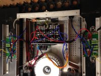
Quite brilliantly (not)I have built an f5 (my first non gainclone diy amp)that requires the heat sinks to be dropped on their sides to get to bias pots. As you can imagine thermal stability at minimal dc offset with heat sinks at this angle was around 70mv different (on both channels) than when the amp was at thermal stability fully assembled. Stupid.


Amp worked perfectly other than this, dead quite, great sound but:
at 10 mins Bias =600mv offset =-37mv
30 mins Bias=570mv offset=+63mv
2 hours Bias=537mv offset=+106mv. Both channels equal. +-24v under load. Stable from then on. This seemed quite a large spread.
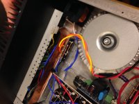
Fiddling around with this awkward arrangement of bias adjustment I added flying leads across the 0.47ohm to track, (as in picture, yellow wires)tacked on with solder. This failed, lead shorted to something, 0.47ohm glowed incandescent. Ooops. Replaced this resistor and initially thought everything OK, but no. I can no longer balance the bias on this channel.
The moral of this story, ALLOW EASY ACCESS TO POTS WITH AMP FULLY ASSEMBLED.
My plans, please comment,
1. Change all mosfetts, and Transistors in broken channel, surely the resistors not effected will still be ok?
2. I have purchased matched LSK Fets from diy store, (awaiting delivery to uk but fantastic service so far) the originals were genuine fets but not matched. Will change both channels. Will properly matched pairs help with the offset spread from cold to hot?
If not could I reduce the value of the compensation thermistor as my bias was Dropping with increased temp?
3. And of course change orientation of 5k pots so I can adjust through access holes in base or put pots on flying leads?
I have lost my nerve and would rather not risk damaging the new matched fets so all advice is welcome. Many thanks in advance.
Thanks guys,
after the glowing 0.47ohm resistor event, replaced the resistor and it biased up fine. It was actually messing with the 5k potts (gluing on bendy adjusters I poured super glue into pot, tried pot , no bias balance, now this seems to be the case with super cheap replacement pots), it no longer bias balances and I have over 1v offset at output.
What would you guys replace? I thought replace both potts and mosfetts, and the currant limiter transistors, and only replace jfets as a last resort. Almost easier to buy and populate a new board.
Before the calamity
Is 120mv dc offset spread, from cold to stable hot 42 degrees C normal any way. could better balnced jfets improve this?
Thanks again
My plans, please comment,
1. Change all mosfetts, and Transistors in broken channel, surely the resistors not effected will still be ok?
Outputs may be smoked, highly unlikely you took out the input pair. The power resistors (feedback and source) should be checked for failure. Resistor can run very hot without failing, so don't assume it is dead.
2. I have purchased matched LSK Fets from diy store, (awaiting delivery to uk but fantastic service so far) the originals were genuine fets but not matched. Will change both channels. Will properly matched pairs help with the offset spread from cold to hot?
If not could I reduce the value of the compensation thermistor as my bias was Dropping with increased temp?
No, and no. The gate drive voltage for the outputs - once set for the difference in the upper and lower devices - is pretty much constant. The big difference is usually due to the temperature variations in the output stage, and that is what causes the offset.
You could change the thermistors, but the reduction of bias with increasing temperature is exactly what is supposed to happen. The thermistors allow a quick warmup and reduce the gate voltage as the amp reaches a target temperature. This ensures that the output does not run away.
3. And of course change orientation of 5k pots so I can adjust through access holes in base or put pots on flying leads?
I would not suggest flying leads for a high impedance drive path between gate and source. The trimmer also carry the AC drive and the leads will have unpredictable results. It may be possible to put the trimmers on 'stilts' and then tilt them up to an angle. You can achieve this by leaving the leads long (insert them very slightly into the pads) or a small (<12mm) extension of their leads made out of leftover component leads.
What I would do is replace the lower L-angle with a flat bar to hold the sinks together.
Then I would use the 64x series trimmers and orient them with the adjust screw facing the bottom of the case.
Finally, get their positions marked out on the case floor and drill two 6mm holes for a screwdriver to enter, and half an eyeball as well.
Thanks Sangram,
So with any luck I will have input jfets for next project .
.
I will proceed exactly as you described, thanks so much for your help.
Prooptiki,
I just increased feedback resistors to 200 ohms each for gain of 10x and a little on board rail capacitance, Otherwise standard F5 Amp. It reached a max steady temperature of 42degrees c so no thermal problems, was completely silent into sensitive speaker. All worked beautifully till I prodded and wiggled my way to ruin in the perfecting of dc offset.
Thanks again for all your input.
So with any luck I will have input jfets for next project
I will proceed exactly as you described, thanks so much for your help.
Prooptiki,
I just increased feedback resistors to 200 ohms each for gain of 10x and a little on board rail capacitance, Otherwise standard F5 Amp. It reached a max steady temperature of 42degrees c so no thermal problems, was completely silent into sensitive speaker. All worked beautifully till I prodded and wiggled my way to ruin in the perfecting of dc offset.
Thanks again for all your input.
- Status
- This old topic is closed. If you want to reopen this topic, contact a moderator using the "Report Post" button.
- Home
- Amplifiers
- Pass Labs
- f5, Bias pots, what NOT to do.