I'm keeping it.
I don't think the imaging is on par with good tubes. Its only working for an hour...
It's not so much a seductive sound but it is impressive and detailed. Cymbals and snare drum brushing have another dimension. Female voices too. Better then B1 R2 with a cap.
I didn't even try a direct coupled B1 R2 because of trust issues when it comes to DC.
Regarding dynamics I only noticed the pot travels less. No gain or loss sound wise with 2x increase in gain and 4x in impedance.
I've gone through B1 original (nice and polite with PIO caps), full passive, Marantz 7 and Matisse clones, b1 r2 with a claritycap esa, iron pre now. Never heard Erykah Badu moaning so much before B1 R2 with a cap, and iron pre is similar I think.
horses for courses
it is possible to make decent B1 + autoformer sounding as tube , but there is a problem ..... whenever I make stage I'm satisfied with ...... it's irrelevant is it made with toobz or sand
my logic is - make preamp invisible as much is possible , add sugar later
and yes , properly regged PSU is a must .... if nothing else , I'm sleeping better
“I didn't even try a direct coupled B1 R2 because of trust issues when it comes to DC.“
Hi Zen
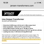
I’m inside my DCB1 now sorting a few issues and adding some Jensen JT-123-FLPH to the output. Is the DC offset something I need to worry about with this circuit? I ask because the Jensen data sheet also mentions feeding them DC free signals (image).
I don’t remember what the offset on the output of the DCB1 was when I fired it up and tested it a few years ago. I don’t think it was anything to worry about, but I could test it again.
Should I be adding something like a 1uf coupling cap in series between the outputs of the DCB1 and the Jensen’s for safety?
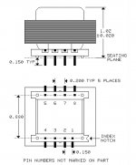
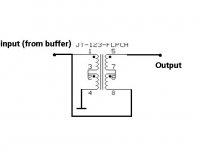
I’m following your wiring guidance diagram for the Jensens. There is a slight discrepancy from the data sheet pin out diagram in that pins 2&3 and 6&7 are reversed from yours. I’m assuming it doesn’t matter as these pins are just linked in series in your diagram (image)?
Another thing I wanted to confirm with your diagram is that the “in” wiring to the Jensens is being run to pins 1&8 in parallel?
Also, should I just connect pin 4 to the output signal ground coming from the DCB1? I’m adding a safety ground to reference the DCB1 board to the chassis at the recommendation of its designer. I could link directly to that point instead. Not sure if it’s a good idea.
Hi Zen
I’m inside my DCB1 now sorting a few issues and adding some Jensen JT-123-FLPH to the output. Is the DC offset something I need to worry about with this circuit? I ask because the Jensen data sheet also mentions feeding them DC free signals (image).
I don’t remember what the offset on the output of the DCB1 was when I fired it up and tested it a few years ago. I don’t think it was anything to worry about, but I could test it again.
Should I be adding something like a 1uf coupling cap in series between the outputs of the DCB1 and the Jensen’s for safety?
I’m following your wiring guidance diagram for the Jensens. There is a slight discrepancy from the data sheet pin out diagram in that pins 2&3 and 6&7 are reversed from yours. I’m assuming it doesn’t matter as these pins are just linked in series in your diagram (image)?
Another thing I wanted to confirm with your diagram is that the “in” wiring to the Jensens is being run to pins 1&8 in parallel?
Also, should I just connect pin 4 to the output signal ground coming from the DCB1? I’m adding a safety ground to reference the DCB1 board to the chassis at the recommendation of its designer. I could link directly to that point instead. Not sure if it’s a good idea.
Attachments
Last edited:
I didn't even try a direct coupled B1 R2 because of trust issues when it comes to DC.
I'm most confused with this. I tried to straighten it out in the "Wayne's 2018 line stage" thread but never did. I was having DC, on fireup as much as 50 mV, after 45 mins or so settling to 3-1.1 mV. (once a smidge over 1 volt) I know the edcor in M2 is said to require no more than 5 mV to avoid saturation and other evils. I don't know if the DC on the linestage output reaches to the edcor in M2 but the notion makes me nervous.
I have heard of using DCB1 and transformer "simple kiss" style, but wondered about the DC on the output of DCB1 and its effect (if any) on M2.
I have also wondered if Wayne's line stage would work "kiss" style with a transformer after out put, but the DC on my linestage caused me concern because it would be paired with M2 and wondered about if its Dc off set would be a problem for M2's Edcore...
Thanks,
Russellc
just quick question for ya Greedy Boyz (having just me legz sticking out of Iron Pumpkin wires) :
is there some pretty famous guy , having gray beard and hair , using complementary JFet buffer in front of xformers ?
also some pretty handsome guy , having just beard gray while hair still gorgeously brown , using same sex JFet buffer in front of xformers ?
if in doubt - measure
xformers are tough little buggers , everywhere enduring for eons various tortures , especially during power up and power down of ......
chrome - measure DC offset behavior of your DCB - power up , cold , hot .... power down
Russell - gimme pics of your Full Nelson line stage ....
Russell - gimme pics of your Full Nelson line stage ....
Ok, not in box yet, looks just like spread out boxless shot 6L6 shows in #1 post, of "Waynes 2019 linestage" thread, same boards. I read that with M2, no more than 5 mV at point going into M2's Edcor transformer. So I wonder if more than that coming out of Wayne 2019 line stage, ( or DCB1) would that not be bad for transformer?
I know I could use cap on output, but trying to keep signal pure as possible. Also, I guess it could be on at all times, like B1, where Waynes linestage sits around <1 mV - 3 mV.
I think I have resolved inability to post pic problem and will do so. Is it wiring you are interested in, or my work on boards? I can show close ups of that work...
Russellc
Good heavens, wait till box comes...leads are longer even than 6L6 shows, wanted enough length to use it box and cut down....not tidy and way not short!
Seems to be a little difficulty with chassis order, accidentally got 2U, cancelled that to get 3U, email confusion resulted it both being canceled. waiting for email to make sure I dont get 2 of them....
Russellc
Seems to be a little difficulty with chassis order, accidentally got 2U, cancelled that to get 3U, email confusion resulted it both being canceled. waiting for email to make sure I dont get 2 of them....
Russellc
just quick question for ya Greedy Boyz (having just me legz sticking out of Iron Pumpkin wires)...
if in doubt - measure...
chrome - measure DC offset behavior of your DCB - power up , cold , hot .... power down...
(Kicks floor sheepishly and shrugs)
 Yeah, I was gonna do that...as soon as I put the pieces back in that I’ve been playing with and changing to crank up the current. (Wanders off daydreaming about how much trouble he’ll get himself into when he gets his hands on that Iron Pumpkin.)
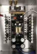
Spent some time yesterday and today making changes to my DCB1 as I could.
I pulled the 220 Ohm series resistors on the outputs and replaced them with jumpers in preparation for the Jensens.
I also decided to change out the current setting resistors I originally installed in the DCB1 to try running it a little hotter.
Afterward, I tested the DC offset several times over during start up, shut down, during warm up and after it had idled for over an hour. The worst offset I saw was -2mV while completely hot on one channel and a similar 2mV jump during several consecutive power cycles.
I’m not sure I’m where I want to be with the current as it only seems to be burning at about 300mA. I may try it as is before turning the heat up again.
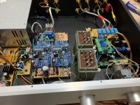
In the mean time, I roughed out a perf board with stand offs to tuck in the chassis by the outputs and started mounting and wiring up the JT-123-FLPH along with some bits for a safe ground I want to install.
I pulled the 220 Ohm series resistors on the outputs and replaced them with jumpers in preparation for the Jensens.
I also decided to change out the current setting resistors I originally installed in the DCB1 to try running it a little hotter.
Afterward, I tested the DC offset several times over during start up, shut down, during warm up and after it had idled for over an hour. The worst offset I saw was -2mV while completely hot on one channel and a similar 2mV jump during several consecutive power cycles.
I’m not sure I’m where I want to be with the current as it only seems to be burning at about 300mA. I may try it as is before turning the heat up again.
In the mean time, I roughed out a perf board with stand offs to tuck in the chassis by the outputs and started mounting and wiring up the JT-123-FLPH along with some bits for a safe ground I want to install.
Attachments
2mV is safe (more than) for autoformer
regarding burned heat in reg - once when you pass double Iq figure (Iq of stage fed with PSU) , if reg is made properly - everything above that is nothing else than ...... heat
example - Good Gemini is programmed for 60mA in case of Iron Pumpkin SE (20ma Iq) and 100mA for Iron Pumpkin (2 x 20mA Iq)
regarding burned heat in reg - once when you pass double Iq figure (Iq of stage fed with PSU) , if reg is made properly - everything above that is nothing else than ...... heat
example - Good Gemini is programmed for 60mA in case of Iron Pumpkin SE (20ma Iq) and 100mA for Iron Pumpkin (2 x 20mA Iq)
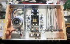
Just finished modifications to my DCB1 based preamp. Now its an IronDCB1.
Jensen’s tucked in the back in series with the outputs. Hopefully the 6dB of gain will help make my phono happier sounding.
I replaced the pots with some proper logarithmic NOS Clarostat units which I bought a batch of off eBay. I matched them for the highest impedance I could find out of 100 I had. My phono has an output impedance approaching 3K, so I figured any help I could find avoiding a mismatch problem I should take advantage of.
In cleaned up and shortened the signal wiring inputs.
Added a new safe ground that connects the circuit board’s central ground to the chassis and lifts it so is supposed to help with any ground loop issues.
I had to pull my fancy TX2575 series output resistors in order for the buffer to be able to drive the transformers, but the remaining other important resistors are all the same or similar quality.
I also adjusted the current setting resistors in the power supply to run it at higher current which is supposed to give me some sonic benefits like improved sound stage and blah blah blah.
Thanks for the advice on the power supply Zen. I was running it pretty cool and only increased it to about 300mA or so. Still not much heat generated, but I had the lid off and have been running it like that since I finished it a couple years ago.
I’d like to finish perforating the lid I made for it and finally put it in place, so I’ll have to monitor the heat build up. Hopefully it won’t be an issue as the entire core of the chassis is 1/8” aluminum plate and acts as an additional heat sink to the ones I made and installed.
Hope to fire it back up later and make sure the offset and heat still seems fine. Any other issues I should check before I try it in my system?
Attachments
Just an update. My Iron-Hypo project appears to be successful.
There were no issues with heat or DC offset at all...actually the offset dropped to about 1.1mV on both channels once I completed all the final connections and retested it before hooking it up.
In my eagerness to give it a listen I had a less than ideal first experience. Part of it was that there was much distraction on the weekend going on about the house.
The first test was with my phono source. Honestly, it left me scratching my head and walking away a bit frustrated. I wasn’t sure things didn’t sound worse.
I was making these modifications with the goal of trying to help my phono source drive my system in a similar manner that I was capable of doing with my CD player. The difference between the two was big and the system sounded much more dynamic and alive with the CD source especially when I was listening to some of my favorite R&B recordings.
When I came back to the system a few days later I listened to it enough to evaluate how much more gain I appeared to have at my disposal.
The CD player had way more gain than it needed. Luckily, the NEC unit I had started using because my old Rotel died has a built in output level pot and I was able to dial it back to the middle of its range so that it seemed to work well with the preamp.
Sometimes I like to be lazy and just stream background music from my iPad. The sound quality is mediocre at best, but is fine for cooking a meal to.
The iPad wasn’t able to match the dynamics of the CD player...maybe because it wasn’t able to produce as powerful an output signal in addition to the lower quality signal. Now it is capable of much more and also seems a good match for the preamp.
I had decided to give the phono another shot and turned my head amp and phono amp on to warm up for a little while while I listened to the digital sources.
Both my head amp and phono amp run on hi capacity NiMH battery packs that I sourced online. I installed voltage meters in them that are set up with a test switch so I can check the battery’s level for the amps before using them.
Well, when I tested the head amp I noticed the voltage had dropped down around 9.8 V, and as I was watching continued to drift down. After almost a year since I had installed it’s battery pack it appeared to finally need charging.
Recharging the head amp battery finally gave me more of the results that I was after. The phono is now able to drive the system to much higher levels. The bass it produces with the slot loaded dipole bass units I just finished is wonderful.
The only issue I have is that in my enthusiasm of finally being able to rock the house with the Black Keys from my phono source I reached a level on the volume control around 2:00 or so where the system seems to start producing uncontrollable lower frequency feedback noise through the speakers. Granted, everyone else in the house was already complaining about the level when the volume was at 12:00")
If I lift the needle off the record the feedback noise will stop. It also subsides if I dial the volume back to about 1:00. I’m not sure if there is another defect in my phono system causing this feedback or if its typical once you reach these levels for this to happen. I’ve not experienced it before, and I have blasted quite a few albums on my parents old Pioneer receiver as a teenager
Perhaps the phono cable is too long or is picking up this noise? Maybe its actually the cartridge stylus experiencing uncontrollable oscillation in the groove? Maybe I need to revisit my tonearm setup?
I tried a few other albums and it does not seem related to the specific recording as regardless to the nature of the material (Jazz, Blues, Acoustic) the same noise occurs once I reach that level in the volume control.
I also compared recordings that I have of the same material on LP and CD which are created from the same masters to evaluate and compare the sonics of the CD versus the phono source.
I was particularly interested in the impression of the bass response. The subject of square wave ringing was brought up in relation to using transformers in the manner in which they are used here. This is not something I was familiar with. My brief look into information I could find on the subject said that square wave ringing and how it may affect the audible range varies by opinion but that it may have an affect on the lower frequency range?
As I mentioned, the overall bass response of the system in general was very satisfying. It is supplemented below 75Hz with a subwoofer. I will say that the CD source of the recordings I compared did seem to have a slight advantage in the area of bass response, but it was not necessarily any better. I found there to be slightly more bass, but the bass gave me the impression of a bloated boomy bottom end.
Not that I don’t like big bottoms...I just don’t enjoy them as much coming from my audio system.
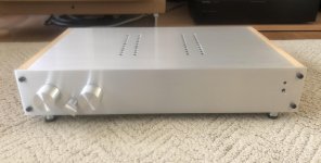
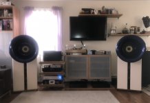
Now I am just trying to spend some time listening to and enjoying music and trying to form a more detailed impression of the system.
Below is a bit of a lousy picture from my phone made worse due to the light from the window behind and a pic of the preamp all buttoned up with a lid and everything for the first time.
I have Lowthers DX3 in the Oris Horns being driven by the humble little ACAs I built with some Semisouth slipped into Q1.
The dipole bass units are loaded with 6 each of those buyout 8” Peerless that Papa came across at Parts Express shortly after he produced the SLOB article. Some old bridged Rotel AV amps drive them.
Signals are managed by a B5.
There were no issues with heat or DC offset at all...actually the offset dropped to about 1.1mV on both channels once I completed all the final connections and retested it before hooking it up.
In my eagerness to give it a listen I had a less than ideal first experience. Part of it was that there was much distraction on the weekend going on about the house.
The first test was with my phono source. Honestly, it left me scratching my head and walking away a bit frustrated. I wasn’t sure things didn’t sound worse.
I was making these modifications with the goal of trying to help my phono source drive my system in a similar manner that I was capable of doing with my CD player. The difference between the two was big and the system sounded much more dynamic and alive with the CD source especially when I was listening to some of my favorite R&B recordings.
When I came back to the system a few days later I listened to it enough to evaluate how much more gain I appeared to have at my disposal.
The CD player had way more gain than it needed. Luckily, the NEC unit I had started using because my old Rotel died has a built in output level pot and I was able to dial it back to the middle of its range so that it seemed to work well with the preamp.
Sometimes I like to be lazy and just stream background music from my iPad. The sound quality is mediocre at best, but is fine for cooking a meal to.
The iPad wasn’t able to match the dynamics of the CD player...maybe because it wasn’t able to produce as powerful an output signal in addition to the lower quality signal. Now it is capable of much more and also seems a good match for the preamp.
I had decided to give the phono another shot and turned my head amp and phono amp on to warm up for a little while while I listened to the digital sources.
Both my head amp and phono amp run on hi capacity NiMH battery packs that I sourced online. I installed voltage meters in them that are set up with a test switch so I can check the battery’s level for the amps before using them.
Well, when I tested the head amp I noticed the voltage had dropped down around 9.8 V, and as I was watching continued to drift down. After almost a year since I had installed it’s battery pack it appeared to finally need charging.
Recharging the head amp battery finally gave me more of the results that I was after. The phono is now able to drive the system to much higher levels. The bass it produces with the slot loaded dipole bass units I just finished is wonderful.
The only issue I have is that in my enthusiasm of finally being able to rock the house with the Black Keys from my phono source I reached a level on the volume control around 2:00 or so where the system seems to start producing uncontrollable lower frequency feedback noise through the speakers. Granted, everyone else in the house was already complaining about the level when the volume was at 12:00
If I lift the needle off the record the feedback noise will stop. It also subsides if I dial the volume back to about 1:00. I’m not sure if there is another defect in my phono system causing this feedback or if its typical once you reach these levels for this to happen. I’ve not experienced it before, and I have blasted quite a few albums on my parents old Pioneer receiver as a teenager
Perhaps the phono cable is too long or is picking up this noise? Maybe its actually the cartridge stylus experiencing uncontrollable oscillation in the groove? Maybe I need to revisit my tonearm setup?
I tried a few other albums and it does not seem related to the specific recording as regardless to the nature of the material (Jazz, Blues, Acoustic) the same noise occurs once I reach that level in the volume control.
I also compared recordings that I have of the same material on LP and CD which are created from the same masters to evaluate and compare the sonics of the CD versus the phono source.
I was particularly interested in the impression of the bass response. The subject of square wave ringing was brought up in relation to using transformers in the manner in which they are used here. This is not something I was familiar with. My brief look into information I could find on the subject said that square wave ringing and how it may affect the audible range varies by opinion but that it may have an affect on the lower frequency range?
As I mentioned, the overall bass response of the system in general was very satisfying. It is supplemented below 75Hz with a subwoofer. I will say that the CD source of the recordings I compared did seem to have a slight advantage in the area of bass response, but it was not necessarily any better. I found there to be slightly more bass, but the bass gave me the impression of a bloated boomy bottom end.
Not that I don’t like big bottoms...I just don’t enjoy them as much coming from my audio system.
Now I am just trying to spend some time listening to and enjoying music and trying to form a more detailed impression of the system.
Below is a bit of a lousy picture from my phone made worse due to the light from the window behind and a pic of the preamp all buttoned up with a lid and everything for the first time.
I have Lowthers DX3 in the Oris Horns being driven by the humble little ACAs I built with some Semisouth slipped into Q1.
The dipole bass units are loaded with 6 each of those buyout 8” Peerless that Papa came across at Parts Express shortly after he produced the SLOB article. Some old bridged Rotel AV amps drive them.
Signals are managed by a B5.
Attachments
Last edited:
LOL...in short: Preamp + Iron =
I think my happiness is in direct proportion to the gain achieved by adding the iron.
So, if you talked to me about how much I enjoy my system now I might sound about 6dB more or twice as enthusiastic as before
Of course I am a greedy boy and happiness is relative to what I lust after next.
As long as the journey doesn’t end I’ll continue to have something to look forward to being happy about.
- Home
- Amplifiers
- Pass Labs
- What's wrong with the kiss, boy?