
A good day
Hi Johannes,
just report to you that I managed to get rid of the output capacitor.
Somehow I wasn't followed your suggestion to series the coils for a gain in inductance, I want to keep the bifilar choke with reversal phasing intact.
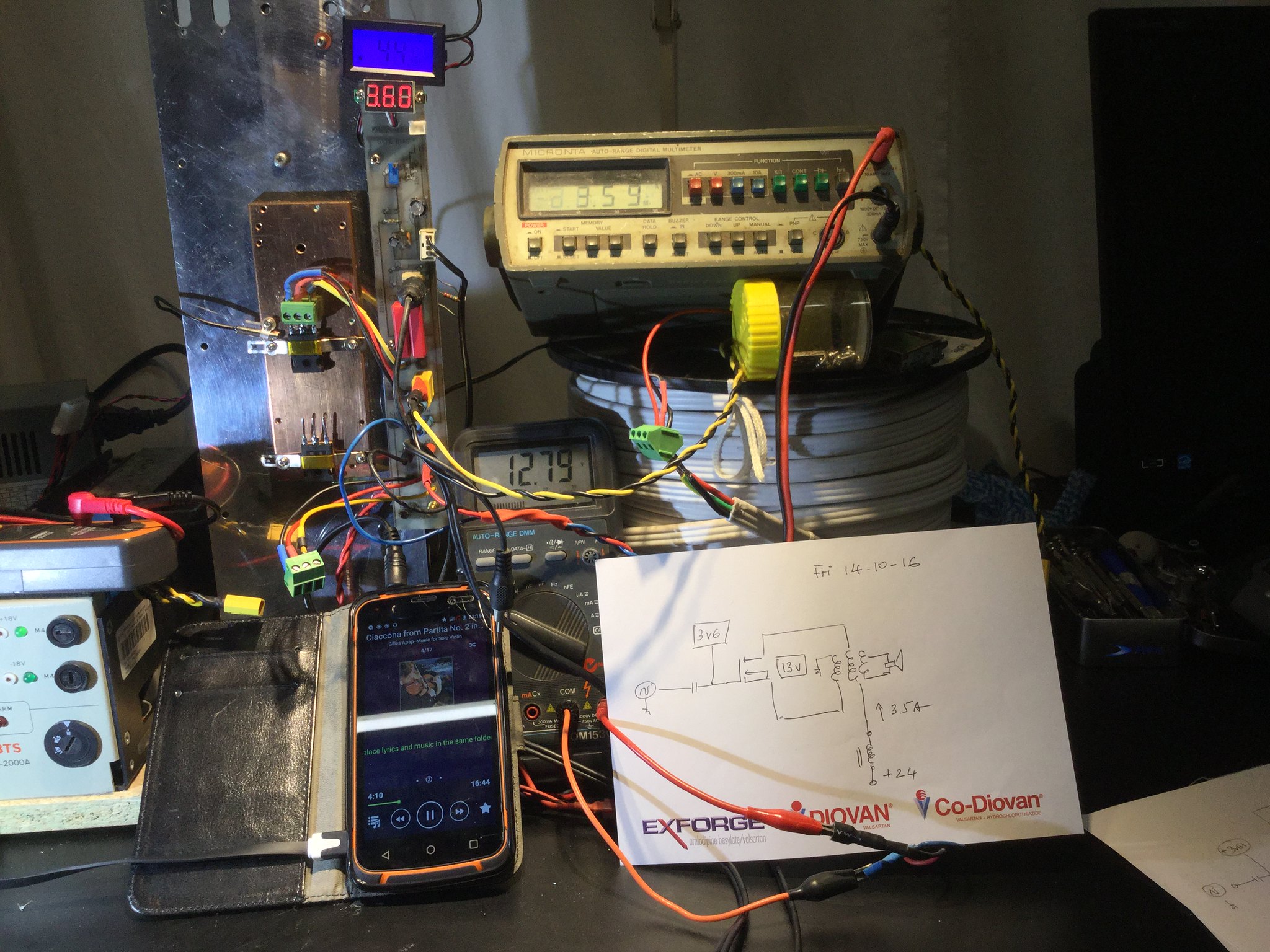
I managed to get an iron core choke, about 2mH, connected to +24v from my PS.
Another break through, I got rid of the output cap and used the third coil from my roll to act as an output, simple as that, pure beauty. Now we have a single fet in push pull mode, hihi, even harmonics will be very low...
The amp is running warm 45deg C, Ids 3.5A, Vds 13V.
To busy with the hardware, just mounted another fet for CCS, hope that will be fine, then at the weekend, I will be able to measure gain and distortion.
Chao
Pascal
Hi Johannes,
just report to you that I managed to get rid of the output capacitor.
Somehow I wasn't followed your suggestion to series the coils for a gain in inductance, I want to keep the bifilar choke with reversal phasing intact.
I managed to get an iron core choke, about 2mH, connected to +24v from my PS.
Another break through, I got rid of the output cap and used the third coil from my roll to act as an output, simple as that, pure beauty. Now we have a single fet in push pull mode, hihi, even harmonics will be very low...
The amp is running warm 45deg C, Ids 3.5A, Vds 13V.
To busy with the hardware, just mounted another fet for CCS, hope that will be fine, then at the weekend, I will be able to measure gain and distortion.
Chao
Pascal
Until I have a basket coil
Hi Johannes,
I have a good weekend, a day earlier than yours.
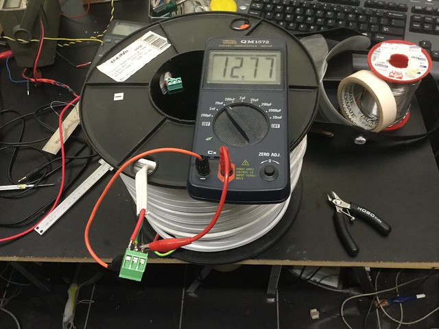
The result is not good, I have to take the blame, 100m electrical wire is not an ideal bifilar choke, due to coupling capacitance around 10nF, like you shunt the fet with a cap of .01uF.
That internal capacitance led me to have false measurement of coil resonance and inductance deduction.
During my Sunday test, I managed to destroy 2 IRFP 7430 when driven with frequency lower than 10 Hz.
Anyway, it was a good experiment, thanks for sharing your thought, I will stay idle until I am able to weave a basket coil with minimum stray capacitance.
Cheers
Pascal
Hi Johannes,
I have a good weekend, a day earlier than yours.
The result is not good, I have to take the blame, 100m electrical wire is not an ideal bifilar choke, due to coupling capacitance around 10nF, like you shunt the fet with a cap of .01uF.
That internal capacitance led me to have false measurement of coil resonance and inductance deduction.
During my Sunday test, I managed to destroy 2 IRFP 7430 when driven with frequency lower than 10 Hz.
Anyway, it was a good experiment, thanks for sharing your thought, I will stay idle until I am able to weave a basket coil with minimum stray capacitance.
Cheers
Pascal
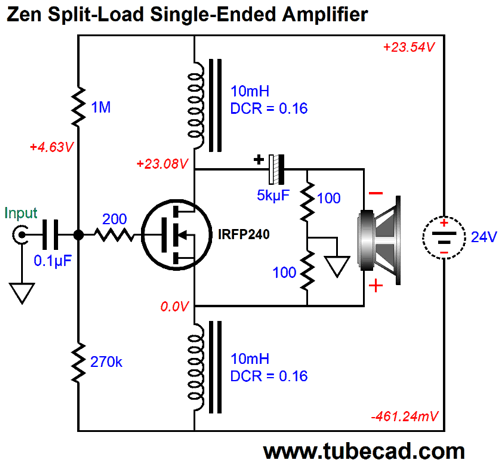
Thanks for your experiments and tests with this split load phase-slitter amp.
There is some (a lot) of interwinding capacitance in the large bifilar coil, but I can't hear any problems with high frequencies or oscillations. The IRFP7430 sounds a little harsh in the top end compared to the IXTK100N25P or the IRLB3813 I have tested. I blame this on the large and quite nonlinear capacitance of the IRFP7430.
I can run any frequency between 1 hz to 20 khz without any problem. I don't understand how your amp could destroy your IRFP7430 devices?
I hope you wind a large 2 x 16 mH (or more) basket weave bifilar coil. I would encourage you to use more then 2 x 16 mH since this inductance value seems to work, but just barely. I wish I had the stamina and economy to buy a couple of 1000 meter spools of 5 mm diameter (19.6 mm2) solid copper cable and wind two large low-dcr 2 x 50 mH bifilar coils.
Cheers,
Johannes
I think that the inductance from my 100m roll is too low as compared to your spices simution.
When I ran less than 10Hz, it does not created enough reactance to govern Ids, then the current went up to self destruction. (The circuit was very stable, no oscillation whatsoever).
https://youtu.be/tGjivFSpe30
IFRP7430 is a gem to me, i took off the bifilar choke, rearranged it to a common source amp with a CCS, it passed my hearing test.


Thanks for the video.
Yes, the IRFP7430 is a fun mosfet.
I made this simple simulation today. It is a transformer-coupled version of the phase-slitter amp. No output cap. I added 100 nF interwinding capacitance to the aircored transformer.
I don't believe the results, even though they should be indicative of a fast, low thd and nice sounding amp. I don't have a correct spice-model of the aircored transformer, so the real world results should be a little worse then the simulation.
My bifilar choke phasesplitter amp sounds just like a very low thd and very high resolution amplifier. It handles complex music at loud levels with ease. It has a very firm, dynamic and "punchy" bassreproduction. a great immediate presence and an organic natural unhindered flow.
I dread rewinding my bifilar chokes to quadfilar aircored transformers.
Even though this idea seems very nice I will probably keep on using my simple capacitor coupled phasesplitter amp.
I guess the transformer-coupled version should be very nice for midrange and treble use in an active xover multi-amp setup. The transformer will keep DC-"thumps" out of the voice-coils during turn on and off.
Cheers,
Johannes
Quad Filar Transformer
Hi Johannes,
Interesting indeed to see you playing with a quad, your dual 16mH coils output to an 8 Ohm speaker let me see the load impedance is merely 4 Ohm per coil, please correct me if I am wrong, your Vds is around 20v, Ids must be very high then?
I am wiring a "positive current feedback by input transformer to my current IRFP7430 set up, hope it will be ready to test by tomorrow with a toggle switch to compare odd and even harmonics with and without PCF that would give me more knowledge about the 7430, then based on those result I will be back to the splitted coils topo. I realised that I don't need 16mH coil if my circuit is using a CCS.
Had a look on your FFT, -80dB the 2nd is unreal, hihi.
Tried to listen to Cristobal, too noisy for me, I prefer the Chinese Basso Zhao Peng for testing my amp, even wouldn't have a clue what he is singing about.
Cheers
Pascal
This is one of John's tutorials, to make some point.
There are many better detailed and documented projects out there which will have far fewer dangling questions for the builder.
All in all, the "MoFo" in this forum section is probably a better plan, and certainly has raised much talk and many happy builders.
There are many better detailed and documented projects out there which will have far fewer dangling questions for the builder.
All in all, the "MoFo" in this forum section is probably a better plan, and certainly has raised much talk and many happy builders.
SLAPS for SLAM!
SLAPS for bass.
Improving SLAPS - introducing X-SLAPS
Here is a lot more information about this kind of amplifier. Lots of measurements, discussion and tests.
SLAPS for bass.
Improving SLAPS - introducing X-SLAPS
Here is a lot more information about this kind of amplifier. Lots of measurements, discussion and tests.
oh, let's inference a little, the signal (alternating current) will be very difficult to pass the inductor and go to ground. Has anyone tried the schematic on tubecad yet? Signal will choose less resistor path (200 + 100 ohm)to go to ground, it causes more effect in mosfet (like capacitor) than design of this thread. The inductor dissipates heat while eliminating interference in the power supply.
- Status
- This old topic is closed. If you want to reopen this topic, contact a moderator using the "Report Post" button.
- Home
- Amplifiers
- Pass Labs
- Split load phasesplitter amplifier with bifilar choke load