
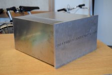
That's the real thing! I like your PSU!
Hopefully a good power plant nearby1
Have fun!
Greets
Dirk
Just kidding! It's built to average specs with two Anteks at 600va and 66,000uF per channel. Not overkill but enough to dim the lights!
")
Regards,
Dan
@Dan was it because of you starting this thing up that triggered the Pickering Nuclear plant alert last week? 
I just realized I have a pair of Antek 6224 stashed away meant for F5T monoblocs. This only requires single rail supply correct? Could I cheat and use standard dual rail FW PSU with 50V caps and take these in series for around 68V unloaded across the +/-?
I just realized I have a pair of Antek 6224 stashed away meant for F5T monoblocs. This only requires single rail supply correct? Could I cheat and use standard dual rail FW PSU with 50V caps and take these in series for around 68V unloaded across the +/-?
Old don't work so we get fresh link to slides BAF Slides Nelson Pass | AudioMaker
Thanks to Mr's Rothacher and Pass
Thanks to Mr's Rothacher and Pass
@Dan was it because of you starting this thing up that triggered the Pickering Nuclear plant alert last week?
I just realized I have a pair of Antek 6224 stashed away meant for F5T monoblocs. This only requires single rail supply correct? Could I cheat and use standard dual rail FW PSU with 50V caps and take these in series for around 68V unloaded across the +/-?
Sorry, slight correction here. I'm using the AN-8445 - 800VA 45V Transformer and it's ideal because it has a 12V secondary that will supply my bias circuit and when combined two 18v secondaries to supply a buffer circuit if required.
And yes each channel requires only a single +ve supply.
Regards,
Dan
I will try...this amp
I made a nightshift - some little progress with my 'optocoupler-boards' (in
point -to-point).
The try continues....
Greets
Dirk
I made a nightshift - some little progress with my 'optocoupler-boards' (in
point -to-point).
The try continues....
Greets
Dirk
Attachments
@ Dirk
Do You want try H2&H3 switch in CCS connection point C and D ?
@ Diyers
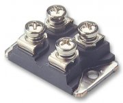
You can get 50 watt's from single transistor in class A
Good news IXYS is back in stock for less 20 €
https://www.mouser.fr/productdetail/ixys/ixfn140n20p?qs=t7yjd2JO/gTEsrKBTipgAg==
https://www.mouser.com/datasheet/2/205/99245-64964.pdf
Do You want try H2&H3 switch in CCS connection point C and D ?
@ Diyers
You can get 50 watt's from single transistor in class AGood news IXYS is back in stock for less 20 €
https://www.mouser.fr/productdetail/ixys/ixfn140n20p?qs=t7yjd2JO/gTEsrKBTipgAg==
https://www.mouser.com/datasheet/2/205/99245-64964.pdf
Attachments
to Soundhappy #968
Hello Soundhappy,
yes I will try the difference in the resistor cascade output (balance 2nd / 3rd
harmonic). I thought about a switch but decided for the screw method.
I am also thinking about a input buffer / driver stage. Nelson Pass recommended
an output impedance of a buffer / driver stage below 100 Ohms. The resistance to ground - then into the transformer....
I see similarities to the M2X.... on the input side. I was thinking about using one of the buffer input boards of the M2X (but voltage difference +-24V / +60V, M2X is complementary and dual rail PSU - 50W-SE-Schade is single ended....) Only some thoughts.
Greets
Dirk
Hello Soundhappy,
yes I will try the difference in the resistor cascade output (balance 2nd / 3rd
harmonic). I thought about a switch but decided for the screw method.
I am also thinking about a input buffer / driver stage. Nelson Pass recommended
an output impedance of a buffer / driver stage below 100 Ohms.
The resistance to ground - then into the transformer....I see similarities to the M2X.... on the input side. I was thinking about using one of the buffer input boards of the M2X (but voltage difference +-24V / +60V, M2X is complementary and dual rail PSU - 50W-SE-Schade is single ended....) Only some thoughts.
Greets
Dirk
@Ben Mah - Your post #950 is absolutely perfect for me. I'm starting to learn a bit mroe and considering dipping my toes into the deeper water... Plus, like you, I have a few of the Tokins left from my SissySIT adventure.
Thanks!

As I have mentioned before, it's worth building. It's my favorite amp and it will stay in use until the weather gets too hot in the summer. Right now it is providing supplemental heating in addition to fabulous music.
Hello Dirk..I thought about a switch but decided for the screw method.
I am also thinking about a input buffer / driver stage. Nelson Pass recommended..
Your tight screw connection do the job as well

One amplifier but with two distinct audio characters to chose
is an interesting DIY option = twice joy with differents audio sources , preamplifiers and speakers
for Your the very best system configuration.
Input buffer can be with 2SK170 or equivalents.
Greetings
..Still a lot of mechanical work. How to position components..
Yes keep distances , wires short if possible..try test psu voltage then CCS and bias circuit, audio path at the end.
Safe step by step method. BTW Nice big chassis

The speaker connection options are definitely worth considering. I did that on my amps with quick connectors.
I have tried some of the connections and I'm not sure of the results. With my THF-51S version, I have found that the H2 varied quite a bit also with power output. More on that later.
One thing that I found was that I preferred the sound with the speaker cable connections inverted for negative phase H2. The amps output positive phase H2 and I found that in my system, at higher volume the sound projected forward too much. I sit about 10 or 11 feet from my speakers and at higher volume the sound was too much in my face. With reversed speaker connection and negative phase, the sound was more in the speaker plane and behind.
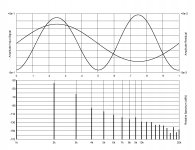
Here is a distortion plot that I did with my Focusrite 2i2 and DiAna software with a 1kHz signal showing the distortion at 1W into 8 ohms at the middle position (C).
I have tried some of the connections and I'm not sure of the results. With my THF-51S version, I have found that the H2 varied quite a bit also with power output. More on that later.
One thing that I found was that I preferred the sound with the speaker cable connections inverted for negative phase H2. The amps output positive phase H2 and I found that in my system, at higher volume the sound projected forward too much. I sit about 10 or 11 feet from my speakers and at higher volume the sound was too much in my face. With reversed speaker connection and negative phase, the sound was more in the speaker plane and behind.
Here is a distortion plot that I did with my Focusrite 2i2 and DiAna software with a 1kHz signal showing the distortion at 1W into 8 ohms at the middle position (C).
Attachments
Last edited:
It's my favorite amp...
Out of curiosity, which amplifiers got downgraded and are next in your list below this one?
This looks like so much fun that I have decided to join the party and build a THF-51S amp. To be truthful, I have listened to Ben Mah's amp and it is very nice sounding.
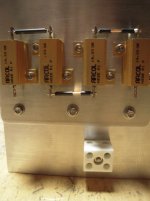
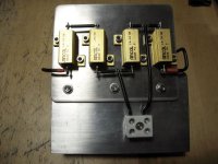
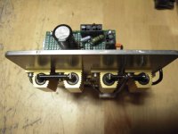
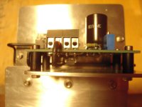
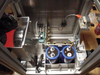
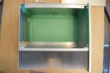
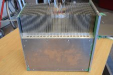
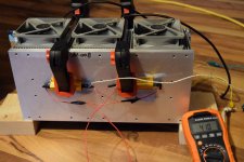
I bought some surplus heatsinks which weigh 11 lbs. (5 kg) each. They are not huge so I knew that some sort of fan cooling would be needed. I wanted to make sure that the fan arrangement that I planned would be adequate before I committed to designing a case so I rigged up a test. Two 8 ohm resistors were clamped to a heatsink and 28 Volts were applied to the resistors in parallel. Three 92mm fans kept resistor temperature to about 41 C. Now I was confident enough to design the cases.
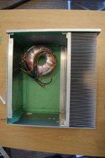
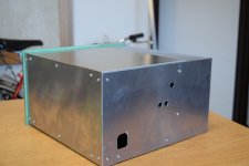
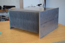
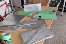
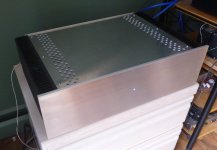
I am building the two cases so I will have monoblock amps. So far, I have all the parts cut to size and have assembled one case. The second case is not too far behind. Just a little bit more drilling and tapping.
The fans will be under the heatsink. I also decided to enclose the heatsink for better cooling efficiency.
I bought some surplus heatsinks which weigh 11 lbs. (5 kg) each. They are not huge so I knew that some sort of fan cooling would be needed. I wanted to make sure that the fan arrangement that I planned would be adequate before I committed to designing a case so I rigged up a test. Two 8 ohm resistors were clamped to a heatsink and 28 Volts were applied to the resistors in parallel. Three 92mm fans kept resistor temperature to about 41 C. Now I was confident enough to design the cases.
I am building the two cases so I will have monoblock amps. So far, I have all the parts cut to size and have assembled one case. The second case is not too far behind. Just a little bit more drilling and tapping.
The fans will be under the heatsink. I also decided to enclose the heatsink for better cooling efficiency.
Attachments
Last edited:
- Home
- Amplifiers
- Pass Labs
- 50w Single-Ended BAF2015 Schade Enabled