Both will dissipate approximately the same amount of heat. The current is identical and the voltage drop across each is intended to be equal or close to equal.
Well then I'm assuming separating them physically will even out the thermal load
on my heatsinks and the components. My CCS at 3.6 amps gets pretty hot!
Regards,
Dan
@ Dan
My are Mr.Pass TL431 psu circuit for bias.
Made with this schematic voltages can be trimmer ( multiturns ) adjustable to 4.7V and up to 12V. Work splendide
Yes. I used the same circuit for the bias.
When I'm done this thing is going to be a MONSTER!

YesI have a monster 12"(31CM)T x 18"(46cm)W x 3"(8cm)D heatsinks for each channel.
I suppose I could get good thermal separation by mounting each IXFN a few inches apart.
Regards,
Dan
Mounting two IXFN at equal distance from the heatsink center and left, right sides for example.Haha better the mono blocks!Yes. I used the same circuit for the bias.
When I'm done this thing is going to be a MONSTER!
With two 600 Watt´s Antek toroids and big psu cap's this stereo amplifier can be lifted only by Arnold Schwarzenegger.
Attachments

Yes
Haha better the mono blocks!
With two 600 Watt´s Antek toroids and big psu cap's this stereo amplifier can be lifted only by Arnold Schwarzenegger.
Zen Mod said go multi kilowatt or go home!
Plus I always build my amps with custom made 6mm panels!THF-51S BAF2015 50W Single Ended Amplifier
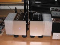
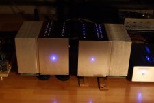
My BAF2015 50W Single Ended amplifiers with THF-51S in place of 2SK77B are finished.
They are monoblocks with CLC supply comprising 2x22mF, Hammond 159ZJ (10mH@5A, 0.16DCR), 2x22mF. Power transformer is Antek AN-6450 (600VA 50V). Under load, the final voltage was 62.5V or so.
Bias supply is TL431 supply (ZenMod schematic) adjusted to provide a lower end voltage of 3.0V to suit my THF-51S Vgs.
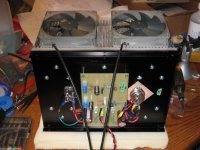
I also did a LM317 supply at 12V to power two low speed (900rpm) Noctua Redux fans. My heat sinks were designed to be force air cooled. They are quite big at about 20 pounds each but they were near 60 degrees C after two hours without forced air. With the fans, they are just warm.
Everything is point to point wiring, from power supplies to amplifier circuitry. Post #857 50w Single-Ended BAF2015 Schade Enabled shows some pictures in addition to the pictures in this post.
I have set the THF-51S Vds at 29V and I is at 3.25A. Initially the current was 3.5A but after some advice from ZenMod (thank you), I lowered the current by increasing the 10K resistor in the CCS to 16K.
I have been listening to the amps for several days now and the sound is very similar to my Hammond 193V choke loaded VFET L'Amp and to my SissySIT. There are probably some differences in sound but all I can say is that I enjoy these SIT amplifiers and would be quite happy to listen to any one of them long term. That said, I really like the sound of this BAF2015 amp. I think it's due to its high power and single ended configuration. It does seem to have a bit more low end heft and it does seem to get my attention a bit more. It's spooky, as ZenMod would say, and this amplifier seems to be more so.
Now I have a pair of monoblocks that double as room heaters for the winter. The SissySit is for the warmer seasons and the L'Amp is for the month or so during the summer when it gets really hot.
My BAF2015 50W Single Ended amplifiers with THF-51S in place of 2SK77B are finished.
They are monoblocks with CLC supply comprising 2x22mF, Hammond 159ZJ (10mH@5A, 0.16DCR), 2x22mF. Power transformer is Antek AN-6450 (600VA 50V). Under load, the final voltage was 62.5V or so.
Bias supply is TL431 supply (ZenMod schematic) adjusted to provide a lower end voltage of 3.0V to suit my THF-51S Vgs.
I also did a LM317 supply at 12V to power two low speed (900rpm) Noctua Redux fans. My heat sinks were designed to be force air cooled. They are quite big at about 20 pounds each but they were near 60 degrees C after two hours without forced air. With the fans, they are just warm.
Everything is point to point wiring, from power supplies to amplifier circuitry. Post #857 50w Single-Ended BAF2015 Schade Enabled shows some pictures in addition to the pictures in this post.
I have set the THF-51S Vds at 29V and I is at 3.25A. Initially the current was 3.5A but after some advice from ZenMod (thank you), I lowered the current by increasing the 10K resistor in the CCS to 16K.
I have been listening to the amps for several days now and the sound is very similar to my Hammond 193V choke loaded VFET L'Amp and to my SissySIT. There are probably some differences in sound but all I can say is that I enjoy these SIT amplifiers and would be quite happy to listen to any one of them long term. That said, I really like the sound of this BAF2015 amp. I think it's due to its high power and single ended configuration. It does seem to have a bit more low end heft and it does seem to get my attention a bit more. It's spooky, as ZenMod would say, and this amplifier seems to be more so.
Now I have a pair of monoblocks that double as room heaters for the winter. The SissySit is for the warmer seasons and the L'Amp is for the month or so during the summer when it gets really hot.
Attachments
Thank you, Bob.
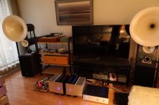
WBS, I am using 19 year old Avantgarde Uno Series 2. Their built-in Sub225 woofer amplifiers have been modified by me. I rearranged the power supply layout and wiring to get rid of their hum, and the parallel output mosfets have been replaced with matched pairs.
WBS, I am using 19 year old Avantgarde Uno Series 2. Their built-in Sub225 woofer amplifiers have been modified by me. I rearranged the power supply layout and wiring to get rid of their hum, and the parallel output mosfets have been replaced with matched pairs.
Thank you, Bob.
WBS, I am using 19 year old Avantgarde Uno Series 2. Their built-in Sub225 woofer amplifiers have been modified by me. I rearranged the power supply layout and wiring to get rid of their hum, and the parallel output mosfets have been replaced with matched pairs.
no porn , no glory!

My BAF2015 50W Single Ended amplifiers with THF-51S in place of 2SK77B are finished..
Congratulations Ben Mah
Superb SIT amp mono blocks.Bravo!Thanks, everyone, for all your wonderful compliments.
Here you go, ZM, some pictures.
I have also included before and after pictures of the Avantgarde Sub225 woofer amplifier (I know it is off-topic so I won't poste any further on this after this post).
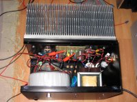
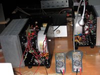
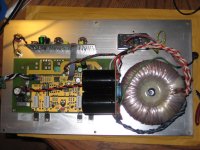
BEFORE: The amplifier has an input board and a main board. The PS rectifiers were located on the main board, with AC wires from the transformer running between the input board and the main board. The AC wires also crossed over the wires carrying the signal from the input board to the main board.
The ground on the main board was in the shape of an "U". The rectifiers, PS capacitor common ground, and speaker grounds were located at the bottom of the "U". The tops of the "U" were at the PS capacitor outputs. The power supply output and ground for V+ was at one side and the output and ground for V- was on the other side. There was audible hum at my listening position when there was no music playing.
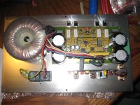
AFTER: The power supply capacitors and rectifiers are on a separate board between the transformer and main amplifier board. AC power no longer goes between the signal input board and the main board. The power supply ground is centrally located between the V+ and V- capacitors, and the ground to the main board is from the output end of the power supply. Only DC and ground is sent to the amplfier board, and the speaker ground is taken off this ground. No audible hum at my listening position.
An interesting observation: There is an input transformer on the input board. However that doesn't solve the problem of internally generated hum.
no porn , no glory!
Here you go, ZM, some pictures.
I have also included before and after pictures of the Avantgarde Sub225 woofer amplifier (I know it is off-topic so I won't poste any further on this after this post).
BEFORE: The amplifier has an input board and a main board. The PS rectifiers were located on the main board, with AC wires from the transformer running between the input board and the main board. The AC wires also crossed over the wires carrying the signal from the input board to the main board.
The ground on the main board was in the shape of an "U". The rectifiers, PS capacitor common ground, and speaker grounds were located at the bottom of the "U". The tops of the "U" were at the PS capacitor outputs. The power supply output and ground for V+ was at one side and the output and ground for V- was on the other side. There was audible hum at my listening position when there was no music playing.
AFTER: The power supply capacitors and rectifiers are on a separate board between the transformer and main amplifier board. AC power no longer goes between the signal input board and the main board. The power supply ground is centrally located between the V+ and V- capacitors, and the ground to the main board is from the output end of the power supply. Only DC and ground is sent to the amplfier board, and the speaker ground is taken off this ground. No audible hum at my listening position.
An interesting observation: There is an input transformer on the input board. However that doesn't solve the problem of internally generated hum.
Attachments

- Home
- Amplifiers
- Pass Labs
- 50w Single-Ended BAF2015 Schade Enabled