Has anyone thought about making a circuit board for this or an aleph ccs . I know it can be done point to point but I would prefer a board.
I'm guessing at some point Papa may do a pcb.
I will probably do one at some stage but not until I have tested a prototype of the amp,
I am still saving my money for the capacitors so haven't built it yet
I'm guessing at some point Papa may do a pcb.
I will probably do one at some stage but not until I have tested a prototype of the amp,
I am still saving my money for the capacitors so haven't built it yet
Those who have a Hammond 193V in the drawer might try to use them in their power supply.
With modest capacitors a ripple of 1mV is possible.

It seems this circuit can easily be converted into a DC-coupled version, but does such a circuit retain the desirable properties (e.g. Schade feedback)? Would there be worries about significant DC offset while the amp comes up to temperature? SPICE suggests it should be a solid performer, but it has lied to me before...
I have four IXFH74N20P that I bought a while ago for a project that has not yet got off the ground which might make a nice scaled-down version of this amp. I was thinking 24V rails and a 2A bias, which makes dissipation for each FET just under 50W. Although the parts are TO-247, they sport considerably lower junction-case thermal resistance than the usual IRFP240. Could I get away running them so hard?
If no one sees any obvious problems with the operating point or DC-coupled circuit, I may start the process of acquiring the remaining parts to give it a go...
Last edited:
in case that I'm not late at least 3 years with my amp schedule , I would squeeze some greenies in this one.......
Care to share the roster of what has been built and what is planned?
what I didn't made and I owe to make :Babelfish SIT-2 , universal ( SIT,SIC,VFet,Mosfet) SE amp , Papa's Sony amp V1 (geschenk from Generg, and kudos for our late friend who made pcbs) ..... to many of these .....
With which SIT devices?
Papa SIT 1
me not worthy
see:
http://www.diyaudio.com/forums/pass-labs/273318-about-possible-babelfish-j-interest.html#post4356779
me not worthy
see:
http://www.diyaudio.com/forums/pass-labs/273318-about-possible-babelfish-j-interest.html#post4356779
Last edited:
Very lucky to have those parts at your disposal, ZM.
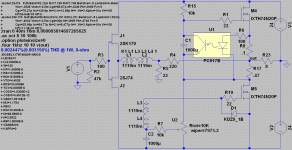
Attached is a draft of my idea for the DC-coupled BAF circuit. I imagine the simulated THD is very optimistic, but does it look workable to others?
(For the record, the .1 + .47-ohm resistors simulate best, but I will have to experiment in the real world to determine which resistor values work best.)
Attachments
Last edited:
Attached is a draft of my idea for the DC-coupled BAF circuit. I imagine the simulated THD is very optimistic, but does it look workable to others?
Looks workable to me.
Probably not necessary but I would want at least 15mA bias out of the push pull buffer.
Maybe cascoded with idss of 15mA
Last edited:
Attached is a draft of my idea for the DC-coupled BAF circuit. I imagine the simulated THD is very optimistic, but does it look workable to others?
(For the record, the .1 + .47-ohm resistors simulate best, but I will have to experiment in the real world to determine which resistor values work best.)
If you have issues with dc offset drifting too much you might need to add 0.1 Ohms at the source of M5.
Start with what you have in your schematic.
Last edited:
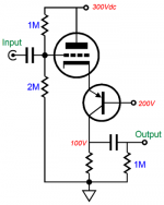
I think someone has been reading the TubeCad Journal.You'll have to explain how that circuit works for my dumb brain, all I see is source follower with cascode.
I can't see how you'll get gain out of that.
The Inverted Cascode
John Broskie would call this an inverted cascode.
Attachments
I think someone has been reading the TubeCad Journal.
The Inverted Cascode
John Broskie would call this an inverted cascode.
It makes perfect sense, just one of those brain fart moments.
I have plenty of those.
")
I think someone has been reading the TubeCad Journal.
The Inverted Cascode
John Broskie would call this an inverted cascode.
Depending how you reference the different devices to ground you can call this an inverted Cascode, a Bastode or a vertical long tailed pair(without the tail)/differential amp. It has been used in RF mixers and (de)modulators since the early sixties (since the first reasonable good RF P-channel devices entered the market).
It is a highly linear and fast little circuit. I am surprised that I have never seen it used in audio before, since it is (was) a very common RF circuit. I am sure someone somewhere use this circuit for audio, but I have never found anyone else then John Broskie (Tubecad) write anything about it.
I first learned about it from a girlfriends father who was a amateur HAM enthusiast who built his gear himself. This was back in 1989. At the time I did not believe it could be used for audio since I did not understand much about electronics.
It dawned on me when reading Nelson Pass articles about the I/V converter and about cascoding that a P-channel device could be used to drive a common gate to get a DC coupled input for signal or feedback, and all of a sudden I remembered this old RF circuit that I had not thought about for many years. I found some nice schematics on Tubecad verifying my ideas so I built a version of it and have been experimenting with it since.
http://www.diyaudio.com/forums/pass-labs/288077-positive-current-feedback-simple-zen-amp.html
Cheers,
Johannes
- Home
- Amplifiers
- Pass Labs
- 50w Single-Ended BAF2015 Schade Enabled