Hi Everyone,
I've been interested in how a high powered, single-ended amp might sound for some time. I suppose a large Aleph could solve that mystery. The BAF2015 SE 50w has a couple of nice twists, one being it uses Schade feedback to give the MOSFET triode like curves. It's also a really simple circuit.
I suppose it's worth while thread to start, unless one was started already.
I searched and went back a few pages, but didn't see anything, so here it is.
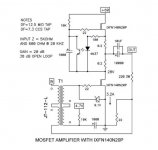
Attached is a screenshot of the schematic with its creator. In the shadows...")
I'll crate a wiki once things get rolling so that FAQ can be answered.
Hope to hear from interested people.
Vince
Notes:
Dave Hill at Jensen, the JT-112-L (what's on the schematic in the video) is an obsolete part number, the part still exists as the JT-123-FL, and the various mounting permutations of that transformer.
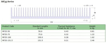
Power transformer: 500va minimum, 600 to 800va recommended.
10k resistor adjustment. See post #49.
To adjust CCS, change .2 Ohm resistors. For example, to lower current by half, increase resistors to .4 Ohm.
Changing The Circuit Voltage:
The question- If I were to lower the voltage of the circuit from 60v to 40v, would the drain of the mosfet be at half the circuit voltage, e.i., 18v-20v?
Is this similar to the ACA bias adjustment? Would I then monitor the drain voltage while adjusting the bias at the gate, arriving at around ~20v?
Answer from ZM- Yup, goal is to have symmetrical behavior of amp's output , in voltage domain .... thus resulting in highest possible power (from voltage window) ..... finally resulting in so-so symmetrical clipping
NP: "If your source is cap coupled, then you will need some resistance to ground.
Try a value like 10K and watch for motorboat (with load). Decrease the
resistance until the motor stops."
Example preamps: BA3- Pre and B1 are cap coupled.
Set input to ground on SE amp input before Jensen input transformer.
NP:
1) The amplifier must be driven by something with a resistive component
to its output impedance. That means that the source cannot be capacitively
coupled, or if it is, there is a resistor to ground after it. Otherwise the
amplifier will motor-boat.
2) The DC Drain voltage of the circuit's gain transistor is temperature
dependent, but it generally should be fairly stable if the heat sinking is
adequate - If it's not stable enough you can put a 5 or 10 watt 220 ohm
resistor from Drain to Source to stabilize it better. I don't think you need
the complexity of a servo.
SoundHappy: [Adjustment of input resistor] Can be done with 10 K potentiometer.
You try find the lower R without motorboat sound , next step measure resistance on potentiometer
then replace potentiometer with fixed resistor who have resistance value close to measurement Enjoy
For more on stabilizing see posts 455 and 456 of this thread.
@ Diyers
Voltage at lead outs of two 1000 uF caps are less 10 V.
10 KuF output cap have 59V for short time at power on.
After few minutes at 3A2 full bias , tension go down to ~ 15 V.
Anyway 50 V rated big can is safe.
I've been interested in how a high powered, single-ended amp might sound for some time. I suppose a large Aleph could solve that mystery. The BAF2015 SE 50w has a couple of nice twists, one being it uses Schade feedback to give the MOSFET triode like curves. It's also a really simple circuit.
I suppose it's worth while thread to start, unless one was started already.
I searched and went back a few pages, but didn't see anything, so here it is.
Attached is a screenshot of the schematic with its creator. In the shadows...
I'll crate a wiki once things get rolling so that FAQ can be answered.
Hope to hear from interested people.
Vince
Notes:
Dave Hill at Jensen, the JT-112-L (what's on the schematic in the video) is an obsolete part number, the part still exists as the JT-123-FL, and the various mounting permutations of that transformer.
Power transformer: 500va minimum, 600 to 800va recommended.
10k resistor adjustment. See post #49.
To adjust CCS, change .2 Ohm resistors. For example, to lower current by half, increase resistors to .4 Ohm.
Changing The Circuit Voltage:
The question- If I were to lower the voltage of the circuit from 60v to 40v, would the drain of the mosfet be at half the circuit voltage, e.i., 18v-20v?
Is this similar to the ACA bias adjustment? Would I then monitor the drain voltage while adjusting the bias at the gate, arriving at around ~20v?
Answer from ZM- Yup, goal is to have symmetrical behavior of amp's output , in voltage domain .... thus resulting in highest possible power (from voltage window) ..... finally resulting in so-so symmetrical clipping
NP: "If your source is cap coupled, then you will need some resistance to ground.
Try a value like 10K and watch for motorboat (with load). Decrease the
resistance until the motor stops."
Example preamps: BA3- Pre and B1 are cap coupled.
Set input to ground on SE amp input before Jensen input transformer.
NP:
1) The amplifier must be driven by something with a resistive component
to its output impedance. That means that the source cannot be capacitively
coupled, or if it is, there is a resistor to ground after it. Otherwise the
amplifier will motor-boat.
2) The DC Drain voltage of the circuit's gain transistor is temperature
dependent, but it generally should be fairly stable if the heat sinking is
adequate - If it's not stable enough you can put a 5 or 10 watt 220 ohm
resistor from Drain to Source to stabilize it better. I don't think you need
the complexity of a servo.
SoundHappy: [Adjustment of input resistor] Can be done with 10 K potentiometer.
You try find the lower R without motorboat sound , next step measure resistance on potentiometer
then replace potentiometer with fixed resistor who have resistance value close to measurement Enjoy
For more on stabilizing see posts 455 and 456 of this thread.
@ Diyers
Voltage at lead outs of two 1000 uF caps are less 10 V.
10 KuF output cap have 59V for short time at power on.
After few minutes at 3A2 full bias , tension go down to ~ 15 V.
Anyway 50 V rated big can is safe.
Attachments
![Screenshot_2016-05-02-22-24-33[1].png](/community/data/attachments/498/498376-3a3ab26e2d5d8c19312b8317d47d7ba0.jpg)
Last edited:
Will you be producing boards or making a prototipe of it?
I can easily see a point-to-point board with this one.
What's the efficiency on this circuit? 20% at best?
If the voltage is dropped to 50v, that's about 30w, correct?
For me 25w to 30w SE with triode curves is still intriguing to me.
Can the circuit scale that way without change any values?
I was thinking of lining up a pair of these HS for one channel.
SIT Amp - Empty hassis - My Photo Gallery
SIT Amp - Empty hassis - My Photo Gallery
Hi Everyone,
I've been interested in how a high powered, single-ended amp might sound for some time. I suppose a large Aleph could solve that mystery. The BAF2015 SE 50w has a couple of nice twists, one being it uses Schade feedback to give the MOSFET triode like curves. It's also a really simple circuit.
I suppose it's worth while thread to start, unless one was started already.
I searched and went back a few pages, but didn't see anything, so here it is.
Attached is a screenshot of the schematic with its creator. In the shadows...
I'll crate a wiki once things get rolling so that FAQ can be answered.
Hope to hear from interested people.
Vince
@ Diyers
You can find and download original correct schematic of hockey puck
Schade Feedback BAF 2015 by this link :
BAF Slides Nelson Pass | Audiohobby.com
Thanks Mr Pass and Mr Rothacher
Greetings
Attachments


Attachments
If I recall correctly from listening to the lecture, Papa Pass accidentally referred to this as a "sh*t" amp, which I got a huge chuckle from. Anyway, I started working up a pcb as I have been wanting to try this since I heard the lecture. I'll post it here when finished, but will need my work thoroughly checked, especially the orientation of the 4N37, as I suffer from dyslexia (as well as a mild form of stupidity). The JT-112 would be mounted remotely (off the pcb).
- Home
- Amplifiers
- Pass Labs
- 50w Single-Ended BAF2015 Schade Enabled