usually, you put there RC for some additional filtering
If it is just for extra filtering, then I assume I can omit if I use 7815 / 7915 regulators with assorted capacitors?
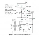
I've been thinking some more about #1198 schematic the more I think the less I understand:
The opamp rails are +-15V and share ground with the amp. Doesn't that mean that regardless of whatever input I use, the output can only swing across +-15V? And since that voltage is the bias, that means that the mimimum bias is -15V relative to Gnd. Or +9V relative to the -24V rail.
Won't that make the minimum possible bias voltage way too high? (The FETs I'm playing with (R100, IRFP150, hockey puck) requires bias in the 1.5V - 6V range for 2A)
That what I thought to solve with the #1196 schematic:
- Power opamp with -24V to Gnd such that it can swing across this range.
- Use resistors to drop the voltage of Gnd from +24V relative to the -24V rail down to +4V (1/6)
- Apply identical resistors to the input signal such that instead of being a signal of 0-48V relative to -24V it is 0-8V.
I tried to simulate all 3 schematics:
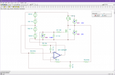
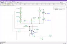
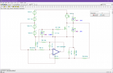
#1198 with opamp, full +-24V rails. Seems to work great.
#1198 with opamp, +-15V rails, not so great. At least in my simulation it breaks down in the way I guessed, the bias can not get lower than ~ 9V which is too high for the FET.
#1196 my idea to pull down the reference voltages towards -24V and use -24V to GND for the opamp. Seems to also work just fine too.
Attachments
A suitable candidate for the 10uF capacitor?
MKP4F051007F00KSSD WIMA | Mouser Canada
Or should I parallel up a few like the Singing Bush?
Regards,
Dan
MKP4F051007F00KSSD WIMA | Mouser Canada
Or should I parallel up a few like the Singing Bush?
Regards,
Dan
Attachments
...having my own struggles, reinventing bloody wheel - wasting my time with tiny sluggish computers (called Arduino)...
")
If you are struggling with Arduino, you are probably not using it the proper way. It is not a full blown computer but rather a drone which repeats the same script until you tell it to stop.
Would you like some help?
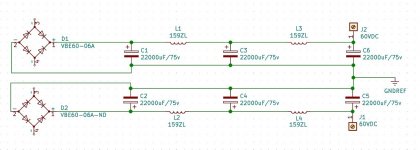
You have the left and right channel grounds of the power supplies connected. To maximize the benefits of dual mono, do not connect the ground of the two channels together. For each channel's power supply ground, provide a separate ground lift thermistor to the chassis safety ground.
The only common connection of power supplies would be the AC to the transformer primaries.
The only common connection of power supplies would be the AC to the transformer primaries.
Last edited:
If you are struggling with Arduino, you are probably not using it the proper way. It is not a full blown computer but rather a drone which repeats the same script until you tell it to stop.
Would you like some help?
tnx Grimberg
need to do my own homework, to learn to catch a fish
coping in fact, done enormous work (results!) in 2 weeks or so, started from 0
You have the left and right channel grounds of the power supplies connected. To maximize the benefits of dual mono, do not connect the ground of the two channels together. For each channel's power supply ground, provide a separate ground lift thermistor to the chassis safety ground.
The only common connection of power supplies would be the AC to the transformer primaries.
That’s an interesting suggestion. I posted the PS schematic to solicit other suggested improvements. I vaguely remember the Aleph class A supplies being bypassed by an electrolytic? Also, I’m pondering some sort of bleed off resistor?
Regards,
Dan
Fit the bleeder on the first cap, decouple the second cap with a 50uF motor run; but your best improvement would be to 'tune' the decoupling across the transformer secondary - Quasimodo time
Simple, no-math transformer snubber using Quasimodo test-jig
Or have a look at Quasimodo results (ONLY) pick a suitable transformer and use the suggested snubber values.
Simple, no-math transformer snubber using Quasimodo test-jig
Or have a look at Quasimodo results (ONLY) pick a suitable transformer and use the suggested snubber values.
Fit the bleeder on the first cap, decouple the second cap with a 50uF motor run; but your best improvement would be to 'tune' the decoupling across the transformer secondary - Quasimodo time
Simple, no-math transformer snubber using Quasimodo test-jig
Or have a look at Quasimodo results (ONLY) pick a suitable transformer and use the suggested snubber values.
I have and have used several times my Quasimodo jig. It works well. The only problem I have is my OScope has died so I'm might be inline of a new one.
Regards,
Dan
Fit the bleeder on the first cap, decouple the second cap with a 50uF motor run; but your best improvement would be to 'tune' the decoupling across the transformer secondary - Quasimodo time
Simple, no-math transformer snubber using Quasimodo test-jig
Or have a look at Quasimodo results (ONLY) pick a suitable transformer and use the suggested snubber values.
Here's something I might refer to since there are alot of similarities to what the Schade needs.
Aleph 1.2 power supply
The above linked Aleph PS is primarily CLC. It has a similar output voltage. And the VA ratings are similar. I'm using one 800VA for each channel.
Regards,
Dan
Yes, a bleeder at the first cap is good. 4K is a good value. I=60V/4000R=0.015A, P=0.015A x 0.015A x 4000R = 0.9W. I would suggest 3W to keep temperature down.
Snubber at the transformer secondary/rectifiers is a great idea. Time for a new oscilloscope.
I believe that a film decoupling capacitor is best located as the last capacitor in the power supply, the one that is closest to the amplifier circuit.
I think 600VA may be enough for the transformer for one channel. 60V x 3.2A = 192VA. I typically mulitply that by 3, so that would give 576VA. However, more will not hurt, except perhaps in the wallet.
Or my back! Everything is going into a single enclosure and the empty case already weighs 50lbs.except perhaps in the wallet.
...I believe that a film decoupling capacitor is best located as the last capacitor in the power supply, the one that is closest to the amplifier circuit...
My bad, I assumed a CRC.
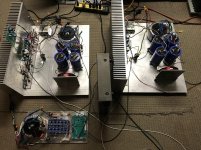
The Singing Bush placeholder a.k.a BAF2015 amp. Completely overbuilt B1 R2 with a 500VA toroid scrapped together with parts laying around....sounds fantastic.
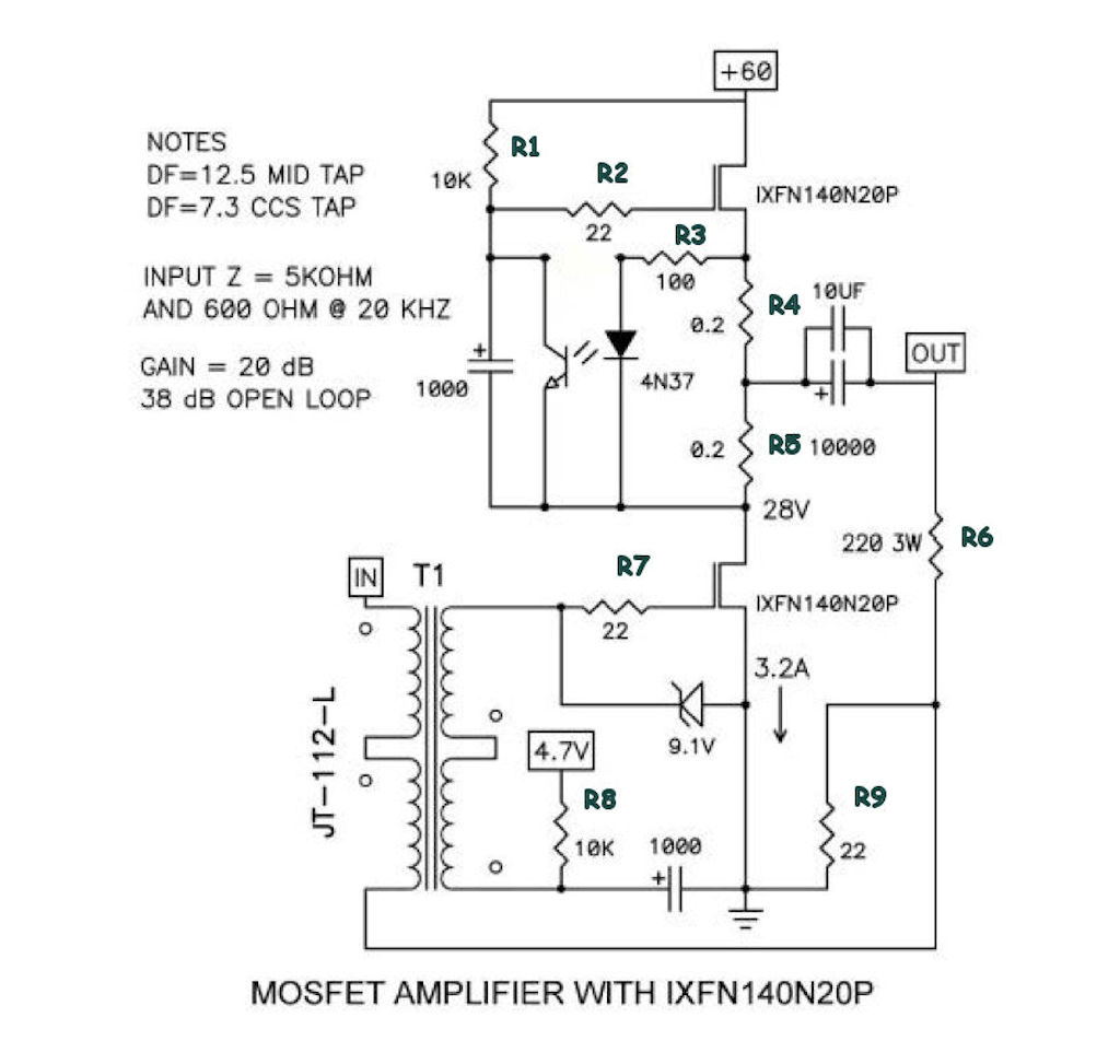
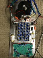
question...I've read the Tokin 2SK182ES needs to have it's bias supply on prior to applying power to the rails. As I'm using IXFN here, does this have that same requirement? I'd like to eventually use just one power switch when I finish the chassis instead of powering up things separately as I'm doing now.
question...I've read the Tokin 2SK182ES needs to have it's bias supply on prior to applying power to the rails. As I'm using IXFN here, does this have that same requirement? I'd like to eventually use just one power switch when I finish the chassis instead of powering up things separately as I'm doing now.
Attachments
- Home
- Amplifiers
- Pass Labs
- 50w Single-Ended BAF2015 Schade Enabled