take in account B1 or something even more elaborate in same fashion , and you're good
considering that you're able to make your own , we can't speak of "limited possibility"
")
for little more headroom just add autoformer ....and that's your own iteration of Iron Pre ( which is practically nothing else than complementary JFet buffer , with decent shunt reg , plus Iron)
considering that you're able to make your own , we can't speak of "limited possibility"
for little more headroom just add autoformer ....and that's your own iteration of Iron Pre ( which is practically nothing else than complementary JFet buffer , with decent shunt reg , plus Iron)
Last edited:


Fantastic Cubicincher!..Most important:
This amp sounds really good. I only listened with the B1 NUTUBE - Pre..
to Soundhappy: changing the output between the resistors will come later.
Schade50 at CCS connection D sound different with H3 dominant
and B1K can be less "wet" with 10.5V ~ 12.5V trimmers adjustements at T7,T8 test points.
+ Fun with phase's etc.
Super flexible preamp & power amp combo.
You can practicaly shape audio signature.
With 100R at B1K outputs possible no need for resistors (motorboating protection) at Schade50 inputs..
Cinemag high nickel transformers are writen at my "things must buy" list.
Have a nice day
I prefer reversed polarity at output of my THF-51S amps also. Regular polarity was too much in my face.
I am changing the operating point following Zen Mod's tests (Singing Bush) , which will lower the H2 - still working on it. The THF-51S at the 2SK77B operation point has quite high distortion.
I have posted some distortion measurements there:
The Singing Bush
I am changing the operating point following Zen Mod's tests (Singing Bush) , which will lower the H2 - still working on it. The THF-51S at the 2SK77B operation point has quite high distortion.
I have posted some distortion measurements there:
The Singing Bush
I am back on the sofa - doing soundtests with reversed polarity at output
of 50W-SE-Schade-amp - this is better!
Dirk

to Ben Mah #1051
Hello Ben,
I seem to like the B1-NUTUBE / 50W-SE - combination more with reversed polarity.
Your measurements (in the 'Singing Bush' - thread) are very interesting!
I will try the other speakeroutput between the resistors this evening.
Have a good day!
Dirk
Hello Ben,
I seem to like the B1-NUTUBE / 50W-SE - combination more with reversed polarity.
Your measurements (in the 'Singing Bush' - thread) are very interesting!
I will try the other speakeroutput between the resistors this evening.
Have a good day!
Dirk
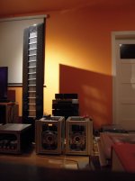
...My THF-51Ss...
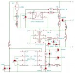
Hi Ben, which bias circuit are you using, is it this one? 50w Single-Ended BAF2015 Schade Enabled
Hi Ben, which bias circuit are you using, is it this one? 50w Single-Ended BAF2015 Schade Enabled
No, I used this one by Zen Mod, with a modification:
50w Single-Ended BAF2015 Schade Enabled
I changed the 1K pot to 5K. That dropped the lowest available voltage from 4V5 to 3V0. If you are using it for the THF-51S amp, you most likely need the lower voltage. It's best to test your THF-51S to determine their Vgs, as 3V0 may still be too high. If that is the case, you can replace the 5K pot with a 5K resistor which will set the voltage at 8V8. Then place the 5K pot across the output, which will then be a voltage divider that will vary the voltage from 0V to 8V8.
The schematic that you referenced is not ideal in that the TL431 is set for 0V to 23V output. For the THF-51S, a maximum of 23V is not required for Vgs.
Here is something that shows how to calculate the resistor values for a TL431 regulator setup, with a sample calculation.
Attachments

I see. I agree with you in that I would question whether I would put a LMC7660 in my amp. My transformer had extra windings so it was easy to just use a separate supply for the bias.
Here is another way:
L'Amp: A simple SIT Amp
I figure my previous post will be useful to some people. Not everyone has the knowledge that you have. As an old saying goes, "Give me a fish and I eat for a day. Teach me to fish and I eat for a lifetime". :
Here is another way:
L'Amp: A simple SIT Amp
I figure my previous post will be useful to some people. Not everyone has the knowledge that you have. As an old saying goes, "Give me a fish and I eat for a day. Teach me to fish and I eat for a lifetime". :
- Home
- Amplifiers
- Pass Labs
- 50w Single-Ended BAF2015 Schade Enabled