Hi, I have a problem with one channel in a Nakamichi PA-7II (220v european version), and I was hoping someone familar with these could chime in..
I tried to attach the service manual, but it is too large. The complete document can be found here:
Nakamichi PA-7 Manual - Stereo Power Amplifier - HiFi Engine
But I extracted the page with schematic of main amp, and that is attached here.
There is a high frequency noise on the right channel, which seems to be around 2 Mhz, with varying strength. I have attached a few pics of output on scope. Test signal is 1Khz sine.
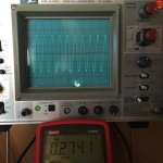
One picture shows just the HF noise present with the amp idling and no input signal. (Time on scope is set at lowest here: 0.5 uSec per division.)
During this test I found a clear connection with Iq (bias) level: The noise would disappear when as I lowered Iq to around 20mV (specification states 40mV). As I raised Iq towards 40mV again, the noise would come back!
At a second test (today) I was unable to replicate this exactly. Now I could just see the problem from the high distortion level at 1w output, and also my oscilloscope actually makes a high pitched whine when I connect the right channel - which does not happen with the left (good) channel.
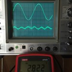
One photo shows distortion residual from HP339 distortion analyzer below the 1w 8ohm output (1 khz sine test signal). The HF noise is clearly visible on the sine output. DMM shows RMS value of amp output.
DC offset is around 4-5mv, so that seems fine.
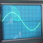
For comparison, I have also attached a pic of the the left channel output, and with distortion residual below. Very nice.
So the fault seems to be related to Iq level, but varies periodically in serverity.
At this point I am thinking defective output transistor, so unless someone has a better idea, I will desolder the source resistors one by one (in pairs), and try to eliminate the fault that way.
But if anyone has seen this issue before (perhaps even on a Threshold of similar design) I would really appreciate your input. Thanks in advance.
I tried to attach the service manual, but it is too large. The complete document can be found here:
Nakamichi PA-7 Manual - Stereo Power Amplifier - HiFi Engine
But I extracted the page with schematic of main amp, and that is attached here.
There is a high frequency noise on the right channel, which seems to be around 2 Mhz, with varying strength. I have attached a few pics of output on scope. Test signal is 1Khz sine.
One picture shows just the HF noise present with the amp idling and no input signal. (Time on scope is set at lowest here: 0.5 uSec per division.)
During this test I found a clear connection with Iq (bias) level: The noise would disappear when as I lowered Iq to around 20mV (specification states 40mV). As I raised Iq towards 40mV again, the noise would come back!
At a second test (today) I was unable to replicate this exactly. Now I could just see the problem from the high distortion level at 1w output, and also my oscilloscope actually makes a high pitched whine when I connect the right channel - which does not happen with the left (good) channel.
One photo shows distortion residual from HP339 distortion analyzer below the 1w 8ohm output (1 khz sine test signal). The HF noise is clearly visible on the sine output. DMM shows RMS value of amp output.
DC offset is around 4-5mv, so that seems fine.
For comparison, I have also attached a pic of the the left channel output, and with distortion residual below. Very nice.
So the fault seems to be related to Iq level, but varies periodically in serverity.
At this point I am thinking defective output transistor, so unless someone has a better idea, I will desolder the source resistors one by one (in pairs), and try to eliminate the fault that way.
But if anyone has seen this issue before (perhaps even on a Threshold of similar design) I would really appreciate your input. Thanks in advance.
Attachments

Hi ...
I have briefly read through your description and my guess (not an expert on this though) would be that the amplifier becomes temporarily unstable due to the likely higher transistor bandwidth when the current is increased (either with the 1 kHz tone or the idle current). Suggestions could be an old electrolytic capacitor (i.e. less efficient HF filtering) or to place some small ferrite toroids on the base(s) of relevant transistors.
Again - not an expert on this so just a suggestion.
Hav en god dag ;-)
Jesper
Thanks for the suggestions, yes I hope Anatech will come by ")
> Mr Pass: The R in the Zobels are fine (unfortunately) - in both channels it measures 5.1, exactly as specs. But your input is much appreciated.
I should add, that the amp looks to have let a relatively "sheltered" life: There are no visible signs of overheating or miscoloring on PCB or any resistors. And all the 2w source resistors measure very close to 1.05 ohm (they are 1R nominal).
Is there a (simple) way to test if the problem lies in the 4 "Stasis" transistors? - as opposed to the "slave" current dumping output transistors? The latter I can test by disconnecting them one pair at a time, but this won't work for the Stasis quad.
Hi jvhb,
I think Nelson nailed that issue down pretty well.
These are normally very stable amplifiers, but losing the zobel would make most amplifiers very unstable. Look at the zobel for overheated resistors. The capacitor needs to be measured as they generally can reduce in value or even open up without showing any outward signs of trouble. For the cost of them, you might be further ahead just replacing them. Don't use a wire-wound resistor in a zobel network as the inductance will take it out of circuit right where it's needed the most.
Absolutely have a good look at the output and driver transistors Look for different date codes on these parts as there might be a fake in there. When these blow up, I replace all the outputs on that channel, and the driver transistors as well. If you install faster drivers, you have to figure out what the new compensation capacitor's value should be. Probably easier to install the originals as 2 picoDumbs discovered.
Nice amp BTW. Extremely reliable and they can sound pretty good. One day I'd like to try one in my new system - just to see how it sounds. It's a keeper though.
Hi Choky,
Many thanks for the kind words. But, I will bet that you knew the answer as well. In this case, being a design that Nelson originated didn't factor into the problem.
-Chris
Thanks for the schematic - I didn't have that.
If the output RC networks are OK, then probably we need to look elsewhere.
In Nakamichi's enthusiasm for wide bandwidth, the II series were given even
faster devices with parallel drivers and so on. As you might imagine, this
trends toward instability, especially when transistors are substituted.
I would suggest that you explore stabilizing the output stage with some
resistance in series with the bases of the transistors. Q114 and Q115 are good
candidates at 100 ohms and Q116 - 119 at 10 ohms.
Hi Nelson,
To be fair to Nakamichi, we never had any series II amps or preamps come in for warranty service. Not even for post warranty service. The only warranty we ever had for the original amps was one (executed by a copper staple for boxes - the giant ones. Staple did not survive the ordeal either.) The other warranty claims we made were for the protection circuit modification to back it off. Nothing ever died in warranty other than the staple incident. I've never, ever seen zero defects like that with any line, not even Revox (who bench tested every single piece before it was shipped out.). We only ever serviced that one PA-7 amplifier, and a CA-7 that met spec, but I had to make it less noisy. That was a challenge as the S/N rating was in excess of 100 dB (can't remember exactly what the spec was).
That was a darned good lineup no matter what people would like to believe. Good design Nelson, and the Nakamichi folks made theirs tough as nails.
-Chris
Hi Chris and Nelson, Thanks to you both for your advice, I really appreciate it.
The Zobel resistor look and measure fine, but I will change them and the cap just to to be sure. What let me to suspect an unstable transistor as such (rather than e.g. a Zobel related issue), was that the HF noise was directly affected by Iq level, even without any input signal or load or the amp. As I understand it, the Zobel only comes in play when there is a signal passing through the amp - but I could be mistaken...
Nelson, I will try your suggestion to add resistance to base of driver transistors. Sorry to keep saying it, but thank you for your help
- Standard 1/4w type resistors should be adequate for this yes?
Hi jvhb,
Yes, 1/4 watt should be okay there. I would tend to use a 1/2 watt part in case you have peak currents that the carbon film types don't handle well. These days the metal film types are so inexpensive that I'll use them even for general applications. The type I would suggest you use is metal oxide. They can take a little more abuse than the standard types (except wire wound, the best for handling current peaks).
The zobel network will be important even without a signal. Even the amplified noise from the circuit itself is enough to take off into oscillation. So signal or not, that zobel network is critical to have in place.
One thing bothers me. These amplifiers are normally very stable. So, what changed? There has to be a reason for your oscillation if the zobel networks are fine. Maybe a driver transistor is going leaky? The output stage is not included in the feedback network, and your problem suggests an issue within the feedback loop.
There is a filter on the input and the diff pair if the zobel is fine. Check C101, C102 and C105. You just never know after this many years.
-Chris
Progress and problems
Hi, I believe I have now fixed the original fault, but there was some unexpected "collateral damage" in the proces. Here is what happended:
In order to check if the output transistors were the source of the oscillation, I disconnected the source resistors for one half of them (in pairs), to leave them passive. Then if the problem was still there, I would do it vice-versa with the other outputs, and that way quickly determine (hopefully) if I should focus on the driver section - and try stabilizing with resistors as previously suggested.
Well I definitely got a result from this, but a bit more dramatic than expected:
After about 20 seconds, the Iq level suddenly went off the charts (I had initially set the Iq level very low), and the amp's fuse popped..
I then checked all the outputs, and Q132R was a dead short.
So this basically meant all new output transistors in that channel, and fortunately I managed to find the correct Sanken devices. After soldering them in, and having checked all resistors and capacitors, I powered it up (using test bulb) but nothing happened! After some investigation, it turned out that the R504 20W R2.2 limiting resistor had burned out in the earlier test - which is a bit worrying.. (The TF501 ought to have prevented this afaik).
After replacing the R504 with a 5W type (while ordering the correct 20w model), I was able to get some initial measurements on the repaired channel, and dial in a little Iq. Everything looked good for around 10 minutes - until the amp switched off again..
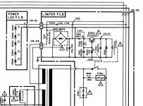
So I had a closer look a the limiter PCB, and discovered that the RY501 wasn't engaging after a few seconds as normal. The relay works just fine, the problem is that it doesn't get the 24DC trigger, so the amp had keept drawing power through the 5W resistor until it gave up.. I believe the problem is the Q501 SC2705 BJT on the Limiter PCB (See schematic in post) - but havn't yet found a replacement.
To sum up:
The oscillation problem seems to have been a leaky/unstable A1492 transistor, that then decided to short out during fault finding (a somewhat "funny" coincidence though..) . But I still need to run a few more tests to be sure the problem is completely fixed.
Questions:
- What would cause the Q501 SC2705 BJT to become defective here? - And can anyone suggest a suitable replacement?
Thanks again for your help.
Hi, I believe I have now fixed the original fault, but there was some unexpected "collateral damage" in the proces. Here is what happended:
In order to check if the output transistors were the source of the oscillation, I disconnected the source resistors for one half of them (in pairs), to leave them passive. Then if the problem was still there, I would do it vice-versa with the other outputs, and that way quickly determine (hopefully) if I should focus on the driver section - and try stabilizing with resistors as previously suggested.
Well I definitely got a result from this, but a bit more dramatic than expected:
After about 20 seconds, the Iq level suddenly went off the charts (I had initially set the Iq level very low), and the amp's fuse popped..
I then checked all the outputs, and Q132R was a dead short.
So this basically meant all new output transistors in that channel, and fortunately I managed to find the correct Sanken devices. After soldering them in, and having checked all resistors and capacitors, I powered it up (using test bulb) but nothing happened! After some investigation, it turned out that the R504 20W R2.2 limiting resistor had burned out in the earlier test - which is a bit worrying.. (The TF501 ought to have prevented this afaik).
After replacing the R504 with a 5W type (while ordering the correct 20w model), I was able to get some initial measurements on the repaired channel, and dial in a little Iq. Everything looked good for around 10 minutes
- until the amp switched off again.. So I had a closer look a the limiter PCB, and discovered that the RY501 wasn't engaging after a few seconds as normal. The relay works just fine, the problem is that it doesn't get the 24DC trigger, so the amp had keept drawing power through the 5W resistor until it gave up.. I believe the problem is the Q501 SC2705 BJT on the Limiter PCB (See schematic in post) - but havn't yet found a replacement.
To sum up:
The oscillation problem seems to have been a leaky/unstable A1492 transistor, that then decided to short out during fault finding (a somewhat "funny" coincidence though..) . But I still need to run a few more tests to be sure the problem is completely fixed.
Questions:
- What would cause the Q501 SC2705 BJT to become defective here? - And can anyone suggest a suitable replacement?
Thanks again for your help.
Attachments
Last edited:
Regarding SC2705 replacement: I has some SC2547E, and after a quick datasheet check I have soldered one in, and it works just fine: Amp powers up and relay clicks. Still don't exactly know why the SC2705 failed in the first place.
However, all is not well, as I now again have a shorted output transistor on that same channel! Seems like that shorted A1492 output may have been an effect rather than a cause.. I suspect it failed due to Iq (bias) run-away (just a theory at this point), so next step will be to try and find what could be causing this issue. Seems to be intermittant, as I had it running for a while with no issues, and then suddenly it goes whammy on me :/
However, all is not well, as I now again have a shorted output transistor on that same channel! Seems like that shorted A1492 output may have been an effect rather than a cause.. I suspect it failed due to Iq (bias) run-away (just a theory at this point), so next step will be to try and find what could be causing this issue. Seems to be intermittant, as I had it running for a while with no issues, and then suddenly it goes whammy on me :/
Update: After desoldering most of the outputs, the shorted devices turned out to be Q120R and Q117R. The Q120 is a regular output transistor, while the Q117 is one of the four Stasis/driver transistors - which were also new. Both are SA1492 PNP. So I still suspect a problem in the Iq/bias circuit, but will leave it for now, and continue fault finding next week... Also need to order new transistors - again.. Qualified advice is welcome..
Bad resistor found
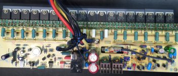
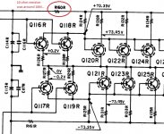
While waiting for new transistors to arrive, I decided to check all resistor values in the channel. I had already checked most resistors earlier on, but had apparently missed R160R on the positive rail, which turned out to be bad: it measured around 16Mohm. See attached photo and detail from schematic (the complete schematic can be found at Hifiengine, see link in initial post). The original was a 1/2w type, and I have replaced it (and the counterpart R161R) with 2w MOX types - which is what I had on hand. These should at least be up the the task.
Now the channel is running with 5 output pairs (two pairs are missing at the moment), and seems to be stable. No noise or oscillation, so thats very good!
I have not found any other defective components (other than the dead outputs), so I think (and hope) this rail resistor was the actual cause of all the problems. Silly that I didn't find this simple fault too start with, but I guess I was overly focused on finding the unstable transistor(s)
The THD in the right channel is however somewhat higher than in the left, and the distortion shape is not nearly as pretty. To match the nice low 2nd-3rd harmonics of the left channel, I have to turn the Iq way up: Around 170mV (and ditto mA) it cleans up very nicely, but that is of course much too hot for continual use.. Will perhaps try with a different "driver quad" and see if it helps.
Will come back with a final update, once I get the two missing output pairs installed.
Attachments
W
I have not found any other defective components (other than the dead outputs), so I think (and hope) this rail resistor was the actual cause of all the problems. Silly that I didn't find this simple fault too start with, but I guess I was overly focused on finding the unstable transistor(s)
The THD in the right channel is however somewhat higher than in the left, and the distortion shape is not nearly as pretty. To match the nice low 2nd-3rd harmonics of the left channel, I have to turn the Iq way up: Around 170mV (and ditto mA) it cleans up very nicely, but that is of course much too hot for continual use.. Will perhaps try with a different "driver quad" and see if it helps.
Will come back with a final update, once I get the two missing output pairs installed.
1 ) I hope you replace all the electrolytics while you are working on it
2) If you have defective transistors in one channel then the bias will also be lower in that channel, hence the reason for higher distortion.
I have not found any other defective components (other than the dead outputs), so I think (and hope) this rail resistor was the actual cause of all the problems. Silly that I didn't find this simple fault too start with, but I guess I was overly focused on finding the unstable transistor(s)
Regardless, you have succeeded in tackling a difficult problem. The value of
that far exceeds the value of the amplifier.
Welcome to FAB.
good job jvhb!
also, FAB ...
i like that.
It begs for t-shirts
mlloyd1
also, FAB ...
i like that.
It begs for t-shirts
mlloyd1
... Welcome to FAB.
- Status
- This old topic is closed. If you want to reopen this topic, contact a moderator using the "Report Post" button.
- Home
- Amplifiers
- Pass Labs
- Nakamichi PA7II: HF noise-oscillation issue