There has been a lot of talk about the First Watt M2 amp by Nelson Pass.
I have become very curious and interested in trying some kind of very simple amp based on an autoformer. The M2 is a little to complex for me at the moment. I would love to build one, even though I have my ideas about possible changes I would make (probably only making it much worse sounding).
The most simple amp based on an autoformer of some kind I could Image is a simple source follower. I wish I had a fist full of Ixys depletion mode fets, but a cheap IRFP150 salvaged from an earlier project will have to do.

This is where I got with the parts I had at home.
I will try a Cree SiC fet soon.
The air-cored autoformer is quite cheap and easy to build. It is 600 turns of 1,5 mm2 electric wire, bifilar wound around a PVC-pipe between two pieces of particle board.
I got the inductance to about 30 mH in an online calculator Coil Inductance Calculator - 66pacific.com
https://youtu.be/Tg-V3i0IUB0
I get a very respectable bass from the amp despite the low inductance. I plan on use two of these for my Faital Pro 3FE20 wide band driver, so it will not have to deal with much below 300 Hz. Today I wanted to test the amp fullrange to see what it could do.
Wih the large and very powerful BIBs I don't need a lot of power from the amp. I could be quite happy with this simple amp, even though I would probably wind on another 200 turns if I wanted to use it fullrange as my main amp.
I guess a nice preamp is needed. The amp has a voltage gain of only 0,47 X, since the autoformer is center tapped to the speaker.
Cheers,
Johannes
I have become very curious and interested in trying some kind of very simple amp based on an autoformer. The M2 is a little to complex for me at the moment. I would love to build one, even though I have my ideas about possible changes I would make (probably only making it much worse sounding).
The most simple amp based on an autoformer of some kind I could Image is a simple source follower. I wish I had a fist full of Ixys depletion mode fets, but a cheap IRFP150 salvaged from an earlier project will have to do.
This is where I got with the parts I had at home.
I will try a Cree SiC fet soon.
The air-cored autoformer is quite cheap and easy to build. It is 600 turns of 1,5 mm2 electric wire, bifilar wound around a PVC-pipe between two pieces of particle board.
I got the inductance to about 30 mH in an online calculator Coil Inductance Calculator - 66pacific.com
https://youtu.be/Tg-V3i0IUB0
I get a very respectable bass from the amp despite the low inductance. I plan on use two of these for my Faital Pro 3FE20 wide band driver, so it will not have to deal with much below 300 Hz. Today I wanted to test the amp fullrange to see what it could do.
Wih the large and very powerful BIBs I don't need a lot of power from the amp. I could be quite happy with this simple amp, even though I would probably wind on another 200 turns if I wanted to use it fullrange as my main amp.
I guess a nice preamp is needed. The amp has a voltage gain of only 0,47 X, since the autoformer is center tapped to the speaker.
Cheers,
Johannes


The Cree SiC fets seems to like more voltage (Vds) then the normal typical IRFP part we use in simple Zen amps. I am going to use my Cree in this amp. I just wanted to test the amp with a simple cheap IRFP150, since it is much cheaper and I have a lot of experience with them. It is easier to evaluate the circuit before using the SiC fets - to get a baseline for comparison. I am going to use my 30 volt power supply later. This is just a first test.
There are a lot of reasons to use a autoformer. They are cheap to make, much more linear and have a very wide bandwidth compared to normal transformers. An autoformer is a great asset in building simple amps. They enable a very wide range of variations in using the devices within their most linear and "nice" range. I want to explore the autoformer because I have a lot of ideas for super symmetrical Circlotrons and other transformer based amplifiers.
I don't like having a source seeing the output without some kind of resistance between. A choke will not shield the source from the speaker, cables and the abundant RF-energy outside the amplifier case as much as a transformer.
Cheers,
Johannes
Last edited:
Autoformers & More MC Pre-Preamps
A great explanation of the benefits of the autoformer.
Cheers,
Johannes
A great explanation of the benefits of the autoformer.
Cheers,
Johannes
")
I have the same question as ZM. The way its connected, the autoformer looks like its doing stepdown duty - not sure if thats for lower output impedance ? Maybe try some other connections eg output taken from the top of the coil (ie at the source of the mosfet) and compare which is nicer ?
I want to use an autoformer in a step down fashion to lower output impedance without excessive use of negative feedback. I believe the autoformer behaves better the a choke, since there is a impedance transformation and a slight "shielding" of the source from the harsh world outside of the amp casing. I wlll test coupling the autoformer as a simple choke, but this is not the way I intend to use it.
This is a gradual step in testing out ideas for an eventual transformer/autoformer coupled amp with some PCF. I believe the autoformer will be less prone to oscillations compared to a straight choke, since there is more resistive losses and a voltage transformation involved. This is not very scientific. It is more based on a hunch and some previous experience with chokes and trifilar wound transformers. Mosfets seems to be quite prone to oscillations without some kind of resistance between their source and the speakers and cables.
If I want to use the Cree SiC mosfets with more voltage, I need some way of increasing the load impedance. A transformer seems like a good simple way. The autoformer seems even better, since you get more inductance with less windings and can use a smaller core (or get more power from the same size of transformer core).
I am very impressed by the soundquality from my simple source follower and air cored autoformer. I did not know 200 meters of cheap PVC isolated 1,5 mm2 wire could make a such a nice sounding autoformer.
Cheers,
Johannes
View attachment 543029
View attachment 543030
Two pictures of the amp. Extreme simplicity. Point to point wiring and some alligator leads connecting the amp to the autoformer.
Hi Johannes
You will be amazed by how much Henry can be trapped in a basket weaving.

Cheers
Mouse H
Hi all
If we look at the amount of copper wire on a planar surface and a cylinder,
for the same number of turn and same inductance
with cylinder radius as a reference,
the planar winding, start from the centre, would use less wire than cylindrical winding.
The magnetic flux inside 1 turn is equals to (regardless of size, shape )
Wb = V x S
defined as 1 Wb (Weber) when
V is 1 volt
S is 1 second
Johnathan inspired me by his 30 mH autotransformer air coiled, I think if the winding will be arranged in a way to use less wire and more inductance that would be a nice touch (nostalgia to basket coil and vacuum tubes) with less capacitance as a bonus
Warm Regards
Johnathan inspired me ...
My apology to Johannes, I misquoted your name.
Would say thank you for this topic.
I am looking for a simple way to drive the power stage.
M2 is a very elegant in its niche, unfortunately I don't have nice IPT and a complementary pair of Fet to play with.
Your approach using air as a media (lossless) solved my concern.
Copy your circuit, I am able to pass as much current as my heart content in the primary coil (your case, an autotransformer, low impedance tap) and not worrying about core saturation by DC current.
(M2 avoided it by using a zero crossing between supply rails, my chapeau Mr Pass, you are a legend).
Cheers

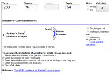
I tried to design a single row multilayer coil with the online inductance calculator
Coil Inductance Calculator - 66pacific.com
With normal 1.5 mm2 pvc covered copper wire it becomes huge!
With only 200 turns it would become 76 cm in diameter. I guess the inductance will be less then calculated due to the spacing of the wires in the basket weave.
This would make for a very sensitive and directional loop-antenna for a crystal-set or a regenerative receiver.
I really like the basket-weave coils, but they seem impractical for transformer/autoformer-duty for audio-frequencies.
Considering the potential benefits of using aircored coils instead of constant current-sources or power-resistors I am a little surprised by their absence. An aircored autoformer can take large currents. It adds a virtual voltage-rail (minus losses) effectively doubling the available voltage-swing. It does not need any cooling.
I hate winding them, but two 100 meter strands of 1.5 mm2 pvc coated copper wires is quite cheap compared to the additional heatsink, transistors, double powersupply voltage etc normally needed.
Cheers,
Johannes
Attachments
The autoformer amp was a test. I developed it further in my thread: http://www.diyaudio.com/forums/pass...asesplitter-amplifier-bifilar-choke-load.html
If the transistor is placed in between the two windings of the auformer where the load normally is attached, you get 3 dB gain and less distortion due to the balanced output canceling second harmonics. The bottom winding is part of a source-follower amp driving the top winding in a push pull arrangement around the load and transistor.
There is lots of potential benefits to the split load phase-splitter amplifier, and it sounds much better (as long as you use a aircored bifilar coil).
With only 2 x 16 mH I get a -1 dB point at about 10 Hz.
Cheers,
Johannes
https://en.wikipedia.org/wiki/Basket_winding
Yes, the basket (weave) windings is used in rf-gear to get a high Q of tuned tank circuits.
It will minimize inter winding capacitance.
Cheers,
Johannes
Yes, the basket (weave) windings is used in rf-gear to get a high Q of tuned tank circuits.
It will minimize inter winding capacitance.
Cheers,
Johannes
- Status
- This old topic is closed. If you want to reopen this topic, contact a moderator using the "Report Post" button.
- Home
- Amplifiers
- Pass Labs
- Inspired by FW M2 AUTOFORMER