Hi Everyone,
I'm a new diyer")
My First build , The AmpCampAmp and the B1.
Today, I want to build a FirstWatt F5
I've buy on DiyAudioStore the LS 2SK170 & 2J74 for this project.
But problems start at the power on ...
Bias ajustement and Offset, No problem
Two channel are biased at 0.5V, and offset under 10mV DC.
Thermal stability after one hour is OK, under 35°c.
I plugged my old test speaker with no load / RCA cinch disconnected : Loud Hummmm on the two speakers …
::: F5 Configuration :::
PSU = 23,7V / 0 / -23,7V
JFet Linear System 2SK170 & 2SJ74
Mosfet IRFP9240 & 240 Vishay.
176 000uF Capacitor bank filter (CRC)
- Amp board INPUT+ ------------> Isolated from enclosure / RCA ( Hot )
- Amp board INPUT GND -------------> Isolated from enclosure / RCA ( Cold )
- Amp board Speaker GND --------> Isolated from enclosure / Speaker ( Cold / Black )
- Amp board Speaker OUT+ --------> Isolated from enclosure / Speaker ( Hot / Red )
- Amp board 24V+ -----> PSU 23.7V+ Rail
- Amp board 24V- -----> PSU 23.7V- Rail
- Amp board 0V -----> PSU 0V Rail
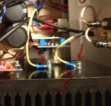
Inside the F5 >http://rockload.free.fr/Images/photo.JPG
Ground Error ? Bad ground wiring ?...
If you're any idea / suggestion for this problem ...
Thank you very much !
I'm a new diyer
My First build , The AmpCampAmp and the B1.
Today, I want to build a FirstWatt F5
I've buy on DiyAudioStore the LS 2SK170 & 2J74 for this project.
But problems start at the power on ...
Bias ajustement and Offset, No problem
Two channel are biased at 0.5V, and offset under 10mV DC.
Thermal stability after one hour is OK, under 35°c.
I plugged my old test speaker with no load / RCA cinch disconnected : Loud Hummmm on the two speakers …
::: F5 Configuration :::
PSU = 23,7V / 0 / -23,7V
JFet Linear System 2SK170 & 2SJ74
Mosfet IRFP9240 & 240 Vishay.
176 000uF Capacitor bank filter (CRC)
- Amp board INPUT+ ------------> Isolated from enclosure / RCA ( Hot )
- Amp board INPUT GND -------------> Isolated from enclosure / RCA ( Cold )
- Amp board Speaker GND --------> Isolated from enclosure / Speaker ( Cold / Black )
- Amp board Speaker OUT+ --------> Isolated from enclosure / Speaker ( Hot / Red )
- Amp board 24V+ -----> PSU 23.7V+ Rail
- Amp board 24V- -----> PSU 23.7V- Rail
- Amp board 0V -----> PSU 0V Rail
Inside the F5 >http://rockload.free.fr/Images/photo.JPG
Ground Error ? Bad ground wiring ?...
If you're any idea / suggestion for this problem ...
Thank you very much !
Ground Error ? Bad ground wiring ?...
First try shorting plugs in the inputs, to make sure there's really a problem inside the amp.
If the noise goes away, either the problem is likely external, or the input cables
between the jacks and the pcb are wired wrong.
Last edited:
I've shorted the Input RCA ( Cold & Hot Shunt ) = No Humm, No Buzz on the speakers.
This humm on speakers without Input RCA is normal ?!
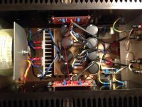
Only one Ground : PSU 0V to 0V Amp Board.
Exact part values used for this project
http://rockload.free.fr/Images/CablageF5.jpg
This humm on speakers without Input RCA is normal ?!
Only one Ground : PSU 0V to 0V Amp Board.
Exact part values used for this project
http://rockload.free.fr/Images/CablageF5.jpg
yeah , I'm puzzled , too
put fat wire bridge between two main pcbs grounds
shortest possible
Attachments
yeah , I'm puzzled , too
[image]Image:F5Gnd|none[/image]
The 0V Power Supply to 0V Board is currently connected !!
Why add a wire bridge between two main PCBs Grounds ?!
_________
[image]Image:My F5|none[/image]
[image]Image:Input wire shield and Enclosure to earth connection.|none[/image]
1 - One link : Enclosure to Earth.
2 - Two link : Shield of the Input Mogami Cable to Enclosure.
See this link : My F5 wiring > http://rockload.free.fr/Images/CablageF5.jpg
I've shorted the Input RCA ( Cold & Hot Shunt ) = No Humm, No Buzz on the speakers.
You have a loop between the RCA barrels and the power supply ground. Both are connected to each other on the boards, and you have connected the two barrels externally to each other through the chassis. If you remove all other wiring drawings, you will see the loop quite easily.
Disconnect the RCA sleeves from the chassis and connect the power supply 0V to the chassis instead. You could use a loop breaker but I don't know if that's legal in your country.
- Status
- This old topic is closed. If you want to reopen this topic, contact a moderator using the "Report Post" button.
- Home
- Amplifiers
- Pass Labs
- F5 - It Works but some problems ...