a choked firstwatt psu
Hi all
I've built some amps in the past, but I'm about to build my first class A amp.
I'm aiming for a +/- 24 volt., 1 to 1.3 Amp as I think that will be enough heat for spanish temperatures.
I'm putting together a PSU for this that I would like to share and hopefully have some feedback on.
Don't know weather to start a new post, but I'll post it here for the sake of the chokes.
The PSU is looking like this:

Some people seem to think that common trafo will give a more coherent sound stage.
R2/3/6/7 is there to separate a bit, the Rground and Lground from each other and the first capacitors.
I did ask Bob Cordell about these. His answer is here.
I guess that with eduard's suggestion here on Lundahl's dual core chokes, that the two coils in one choke would take position of R1 and R2.
My thoughts are to replace R1/4/5/8 with chokes.
I have done some simulation in PSUD2.

This is not all correct as C1 would have 2.6A load
I have made some graphs to show the simulated influence of the chokes

The first 2 are 0.2Ω (which is fairly common) and 0.4Ω which is the R1 R2 configuration above.
Then starts the 2.5mH up to 60mH.
If we take away the 2 resitor poles we get this.

For this particular circuit / values it seems like 20-30mH is more or less the point of diminishing returns.
So, if we put 30mH chokes in these positions, will there be any influence on bass transients.
My guess is that with class A currents and 40.000µF after the choke, this is a non issue, espessially with high efficient 8Ω speakers.
Another issue.
The capacitors for this circuit is
C1 is Epcos B41550 22.000µF, ESR 10mΩ
C3/5/7 is Kemet PEH169, 10.000µF, ESR 16mΩ
C9 is Epcos B41550 10.000µF, ESR 27mΩ
I have seen several places mentioned that capacitors with low ESR are not suited for class A PSU, but never any numbers.
Are theese low ESR for class A and if so why.
Where is this cliff for class A low ESR.
This information may be hidden in the lots of firstwatt build threads, but that's it, can't find them.
All the best.
Hi all
I've built some amps in the past, but I'm about to build my first class A amp.
I'm aiming for a +/- 24 volt., 1 to 1.3 Amp as I think that will be enough heat for spanish temperatures.
I'm putting together a PSU for this that I would like to share and hopefully have some feedback on.
Don't know weather to start a new post, but I'll post it here for the sake of the chokes.
The PSU is looking like this:
Some people seem to think that common trafo will give a more coherent sound stage.
R2/3/6/7 is there to separate a bit, the Rground and Lground from each other and the first capacitors.
I did ask Bob Cordell about these. His answer is here.
I guess that with eduard's suggestion here on Lundahl's dual core chokes, that the two coils in one choke would take position of R1 and R2.
My thoughts are to replace R1/4/5/8 with chokes.
I have done some simulation in PSUD2.
This is not all correct as C1 would have 2.6A load
I have made some graphs to show the simulated influence of the chokes
The first 2 are 0.2Ω (which is fairly common) and 0.4Ω which is the R1 R2 configuration above.
Then starts the 2.5mH up to 60mH.
If we take away the 2 resitor poles we get this.
For this particular circuit / values it seems like 20-30mH is more or less the point of diminishing returns.
So, if we put 30mH chokes in these positions, will there be any influence on bass transients.
My guess is that with class A currents and 40.000µF after the choke, this is a non issue, espessially with high efficient 8Ω speakers.
Another issue.
The capacitors for this circuit is
C1 is Epcos B41550 22.000µF, ESR 10mΩ
C3/5/7 is Kemet PEH169, 10.000µF, ESR 16mΩ
C9 is Epcos B41550 10.000µF, ESR 27mΩ
I have seen several places mentioned that capacitors with low ESR are not suited for class A PSU, but never any numbers.
Are theese low ESR for class A and if so why.
Where is this cliff for class A low ESR.
This information may be hidden in the lots of firstwatt build threads, but that's it, can't find them.
All the best.
See my post #54. I have built single ended Class A amplifiers with that power supply and they are quiet with 103dB speakers. I believe the ripple is around 2mV or so according to simulation.
Your simiuation with a higher inductance and higher DCR choke resulted in 0.5mV ripple. Is that level of ripple necessary really necessary? The higher DCR is a disadvantage. If you worry about bass transients, low DCR is better than high DCR.
Low ESR is not a problem for regular CLC and CRC power supplies. Low ESR capacitors can handle ripple better in terms of better filtering and less temperature gain.
I believe one advantage of dual mono is that it is easier to control hum that may be there if the power supply is shared by two channels (cross channel noise).
Thanks for your reply Ben.
I had a closer look at your post #54.
In your simulation you have used a choke value 10mH 160mΩ
which seems to be the values for 159ZJ.
The next one up is 159ZG at 15mH 250mΩ 4A.
This is probably still a low enough DCR.
I think I'll go with this one.
The next one is 159ZE 28mH 430mΩ, which may be a bit high on the DCR.
In the sims the DCR does not seem to affect the ripple but what voltage you are left with at the output.
I will be using a LT320 based recitifier, so I will gain a bit a bit of voltage there.
I think you are right that the ripple we are left with after a 10-15mH choke is good enough.
You seem to have had good reults with it.
I will no more worry about low ESR capacitors for class A, thank you.
Stay safe
Hi again
Inspired by Ben's simplistic psu in post #54 (thank's again) and bemused by my own ability to overthink and complicate, I have done some more simulations in PDUD2.

I have found the following:
L1 = 15mH (250mΩ) R1 = 0.25Ω ripple = 0.487mV @1.3A load
L1 = 15mH (250mΩ) R1 = 0.001Ω ripple = 0.892mV @1.3A load
L1 = 10mH (160mΩ) R1 = 0.001Ω ripple = 1.344mV @1.3A load
L1 = 10mH (160mΩ) R1 = 0.001Ω ripple = 2.597mV @2.6A load
Looking at this and wanting to reduce the supplys DCR for better dynamic loading, I now think the Hammond 159ZJ @ 10mH (160mΩ) is a better choice.
I have simplified my PSU to This:

I have removed the resistors before the last capacitor.
C9,C10 and C19,C18 is ment to be very near the amplifier boards.
R3 and R4 was ment to make a little distance between right and left earth, but they will most likely go as well.
I have in the past built with mono supplies, but this time I thoght I would try the single one and see if I can beat the hum deamon
An other question : I see that most of you like to use very thick cable in the psu, what gauge is thick?
I have some nice NeoTech STDCT-18, which is AWG 18, 13.5A rated.
Is this cable rated to thin for firstwatt?
If so is there any recomended cable/gauge?
All the best
Inspired by Ben's simplistic psu in post #54 (thank's again) and bemused by my own ability to overthink and complicate, I have done some more simulations in PDUD2.
I have found the following:
L1 = 15mH (250mΩ) R1 = 0.25Ω ripple = 0.487mV @1.3A load
L1 = 15mH (250mΩ) R1 = 0.001Ω ripple = 0.892mV @1.3A load
L1 = 10mH (160mΩ) R1 = 0.001Ω ripple = 1.344mV @1.3A load
L1 = 10mH (160mΩ) R1 = 0.001Ω ripple = 2.597mV @2.6A load
Looking at this and wanting to reduce the supplys DCR for better dynamic loading, I now think the Hammond 159ZJ @ 10mH (160mΩ) is a better choice.
I have simplified my PSU to This:
I have removed the resistors before the last capacitor.
C9,C10 and C19,C18 is ment to be very near the amplifier boards.
R3 and R4 was ment to make a little distance between right and left earth, but they will most likely go as well.
I have in the past built with mono supplies, but this time I thoght I would try the single one and see if I can beat the hum deamon
An other question : I see that most of you like to use very thick cable in the psu, what gauge is thick?
I have some nice NeoTech STDCT-18, which is AWG 18, 13.5A rated.
Is this cable rated to thin for firstwatt?
If so is there any recomended cable/gauge?
All the best
I use 18 AWG solid core copper wire for 2.5 Amp class A amp power supplies. I use it for point-to-point wiring (no circuit board) and keep the lengths short.
The power supply ground connections to chassis should be at the output end of the power supply, though. This will give you a cleaner ground reference.
The power supply ground connections to chassis should be at the output end of the power supply, though. This will give you a cleaner ground reference.
Thanks for your replies.
pinholer; I had a look at your pictures in the 50w Single-Ended BAF2015 thread. So do you use veroboards and make the nessesary connections with said 18 AWG wire? That sounds like a good idea.
If i were to have power supply ground connections to chassis from the output end of the power supply, I gues I would have to make it mono supply or knock the two channels together.
The third alternative would be to have two connections to chassis; one from left and one from right ground, which may not be such a good idea.
Ben; yes I am trying to isolate left and right supply and hopefully end up with a clean Lground (star) and a clean Rground (star) away from the noisy ground point between C1 and C2.
The diagram above show how I would do the actual wiring of the supply.
Please do enlighten me if this may not be such a good idea.
All the best.
I don't see a problem with with isolating the two channels of power. I think it is worth the extra parts and real estate required. The only thing that I question and you did too is whether the 0.2R is needed in the grounds of the two channels.
I would do two ground lifts though, at the left and right channel outputs.
I would do two ground lifts though, at the left and right channel outputs.
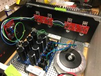
159ZJ upgrade done to my F5s a few months ago.
Previous CRC measured about 50mV of ripple and has the triangular peak as mentioned. After the upgrade ripple dropped down to 2mV or so and was tough to capture. The shape is more rounded with reduced HF noise component.
You guys are welcome to run simulations all day, but in case you all missed the post I made to revive this year old discussion you can have a look at real world results that confirm your sims pretty close. Check original post if pics dont load from this quote.
Hello Jason
Thanks for reminding us and reviving this interesting thread.
I guess we start with simulations to find how it works and hope it will be the same when we build.
Yours, Ben's and other builds show that will be the case with regards to a choked PSU.
All the best.
Thanks for reminding us and reviving this interesting thread.
I guess we start with simulations to find how it works and hope it will be the same when we build.
Yours, Ben's and other builds show that will be the case with regards to a choked PSU.
All the best.
I'm getting close to utilizing my 10 yr-old pair of 159zl along with the diyaudio store power supply board, and I'm hung up on how to (excuse me for using the overly technical terms here) attach the big fat wires of the chokes to the little PC board holes. Does anyone have a good solid connection scheme to share? TIA - Pat
I'm getting close to utilizing my 10 yr-old pair of 159zl along with the diyaudio store power supply board, and I'm hung up on how to (excuse me for using the overly technical terms here) attach the big fat wires of the chokes to the little PC board holes. Does anyone have a good solid connection scheme to share? TIA - Pat
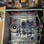
I did this with a pair of F5 V3 Turbo's last year. You can't see the details in the picture because I did the connection under the board.
What I did was drill the holes out a little where you would put resistors, bent bare romex into a U, and put the bent romex into the holes. I drilled the holes so the romex would be a very tight fit, so there would be copper left, and I recall making sure both sides of the board had a good solder connection. The end result was a set of "loops" that I could attach the fat choke wires to. I connected under the board for a clean look up top.
Attachments
Last edited:
Thanks, that's kind of what I was trying, but with single cut off and bent resistor leads instead of Romex, and thus "hooks" rather than loops. You can understand my concerns about the robustness of the connection.
I've been looking at other possibilities, and there is this:
1780507 Phoenix Contact | Mouser
I'd use four of them, one before and one after the resistor span, for plus and minus supply sides. The 7.5mm pitch would give me two solder joints on each of the terminals to make a solid anchor point, and the terminals would accommodate the Hammond leads.
I've got time to think about it, and I'm really in no hurry to totally dismantle my working M2X to get it done. The assembly of the chassis was a bit ... fiddly, as I recall.
Just ordered 159ZL's.
I think the resistor eyelets are pretty sufficient in connecting both sides of the power supply PCB. I will "reinforce" this with short pieces of solid core copper wire (28 pieces required), that I will feed through each eyelet, and then solder at either PCB side. This will create a very high current-capable path between the first capacitor bank, the choke, and the second capacitor bank. The choke wire ends can then be laid flat on the bottom copper fills (I am planning o lay at least 15mm-long length), and then use good solder and my capable 80W soldering iron to finish the job.
I do have a slight worry, though... with the approach I outlined above, the series resistance that may be required to dampen the choke, will be virtually 0 ohms, and this could cause ringing. Maybe leave the full length of choke fly leads, i.e. not shorten the fly leads and use them (I think there should be at least 20cm of length there available) as a bit of series resistance? I want to avoid inserting the resistors here at all costs, if possible...
Last edited:
I'm getting close to utilizing my 10 yr-old pair of 159zl along with the diyaudio store power supply board, and I'm hung up on how to (excuse me for using the overly technical terms here) attach the big fat wires of the chokes to the little PC board holes. Does anyone have a good solid connection scheme to share? TIA - Pat
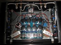
Look at the schematic of the ps board and use the largest non used holes,there should be 2 on each half that you can use.The choke wire is maybe 16 gauge?I used existing holes (can't remember which ones) and didn't have to solder in jumpers or other garbage,its not needed.
What drives you to say to others they are implementing garbage?
Do you have any idea of what was mentioned in the last few posts & the reasons behind such approaches?
It is obvious that you have not implemented the chokes. If you had, you would not post that stupid reply. There are no larger resistor' holes; all holes are of the same, very small diameter - the holes you are referring to are for the ground connections. Do you understand that the chokes are not supposed to go in there?
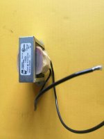
Have a look at the chokes' fly leads wire diameter and then reply again explaining how to feed that wire diameter into the PCB.
According to your rude reply: "there should be 2 on each half that you can use". Show me how...
Do you have any idea of what was mentioned in the last few posts & the reasons behind such approaches?
It is obvious that you have not implemented the chokes. If you had, you would not post that stupid reply. There are no larger resistor' holes; all holes are of the same, very small diameter - the holes you are referring to are for the ground connections. Do you understand that the chokes are not supposed to go in there?
Have a look at the chokes' fly leads wire diameter and then reply again explaining how to feed that wire diameter into the PCB.
According to your rude reply: "there should be 2 on each half that you can use". Show me how...
Attachments
Could you ‘butt splice’ a smaller gauge wire onto the chokes leads that would be a better fit for the board? Crimp on connectors are cheap and easy to use.
https://www.mouser.ca/ProductDetail/TE-Connectivity/2-34067-1/?qs=2ECNu9wPwy5ABWdBJ4JTjg%3D%3D
Regards,
Dan
https://www.mouser.ca/ProductDetail/TE-Connectivity/2-34067-1/?qs=2ECNu9wPwy5ABWdBJ4JTjg%3D%3D
Regards,
Dan
- Status
- This old topic is closed. If you want to reopen this topic, contact a moderator using the "Report Post" button.
- Home
- Amplifiers
- Pass Labs
- Hammond 159zl as clc choke