Papa used to recommend Erse inductor for CLC. More R but less expensive option.
Erse Electronics Inductors
Yes, in Zen1 article he used 4mH 14gauge.
Look at page 3.
http://www.firstwatt.com/pdf/art_zv1.pdf
My Aleph 2 monoblocks (10 years old) use 2.2mH 1.4mm (15 AWG) Intertechnik air coils.
I just checked and they are still available.
https://www.intertechnik.de/Shop/Fr...en/140mm-Luftspule/_LU7822140_1768,de,64,3397
I just checked and they are still available.
https://www.intertechnik.de/Shop/Fr...en/140mm-Luftspule/_LU7822140_1768,de,64,3397
Attachments
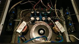
Fitted the 159ZJ into my F4 and so far so good. voltage measurements with .1ohm resistance was +22.7v / -22.7, and with the chokes it is +23.2v / -23.1v which is just fine.
I could convince myself the low frequency response sounds better defined and less muddy, i.e. when listening to the riff of a bass player in a song. But then again, there is that "confirmation bias" phrase nagging at me.
They fit, they work, and there is no noise issues so i am calling it a success.
I just put the same chokes in my clone F7 and I agree with the comment about the bass.More authority for sure.
159ZJ upgrade done to my F5s a few months ago.
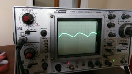
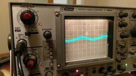
Previous CRC measured about 50mV of ripple and has the triangular peak as mentioned. After the upgrade ripple dropped down to 2mV or so and was tough to capture. The shape is more rounded with reduced HF noise component.
Can confirm after 3 months of use there is a definite change in sound. I did this upgrade to a pair of F5 that I use in an active setup for mids and tweeters. Detail, extension, smoothness have all increased. I am more frequently getting surprised by a soundstage that is well beyond the sides of my speakers with great depth. 98dB midrange which I could noticeably hear several dB decrease in hash, 120hZ hum and noise when ear within an inch of the cone. Now have the blackest of backgrounds, the noise floor of my room is higher and acoustic cues on the record pop out with much greater ease.
For the cost and time this is a very worthwhile and all my future Pass builds will have choke filtering.
Attachments
Hello,
Usually people worry about high dcr when using higher mH chokes in higher current designs.
I presume the R in the CRC power supplies here is usually around 0,5 ohm. A few weeks ago i visited the Lundahl website to download some info and saw there are now a few more '' high current chokes '' available . If you are scared about high dcr most of them will offer lower dcr by putting the two windings in parallel .
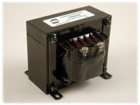
The Hammond usually chosen here are 10 mH and have a nicer price. The Lundahl offer a better construction ( their anode chokes use the same style) more mH ( going from 10 to 40 or more) but they can be a little bigger and are surely more expensive but they last a life time.
Greetings, Eduard
Usually people worry about high dcr when using higher mH chokes in higher current designs.
I presume the R in the CRC power supplies here is usually around 0,5 ohm. A few weeks ago i visited the Lundahl website to download some info and saw there are now a few more '' high current chokes '' available . If you are scared about high dcr most of them will offer lower dcr by putting the two windings in parallel .
The Hammond usually chosen here are 10 mH and have a nicer price. The Lundahl offer a better construction ( their anode chokes use the same style) more mH ( going from 10 to 40 or more) but they can be a little bigger and are surely more expensive but they last a life time.
Greetings, Eduard
159ZJ upgrade done to my F5s a few months ago.
Previous CRC measured about 50mV of ripple and has the triangular peak as mentioned. After the upgrade ripple dropped down to 2mV or so and was tough to capture. The shape is more rounded with reduced HF noise component.
Can confirm after 3 months of use there is a definite change in sound. I did this upgrade to a pair of F5 that I use in an active setup for mids and tweeters. Detail, extension, smoothness have all increased. I am more frequently getting surprised by a soundstage that is well beyond the sides of my speakers with great depth. 98dB midrange which I could noticeably hear several dB decrease in hash, 120hZ hum and noise when ear within an inch of the cone. Now have the blackest of backgrounds, the noise floor of my room is higher and acoustic cues on the record pop out with much greater ease.
For the cost and time this is a very worthwhile and all my future Pass builds will have choke filtering.
Your update is very encouraging for me as I'm currently in the process of building a CLC supply for my F6, so thank you for posting it.
Got a bit crazy and decided to try the Hammond 195G10 (5mH @ 10A) which, due to size, means moving to a 400mm length case. I'm a bit worried that EM radiation from the chokes may interfere with the Jensen transformers on the amp boards though, so I've also got iron covers for them in the hopes of mitigating that.
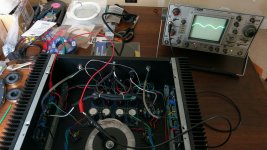
Is measuring the ripple with a scope just a matter of connecting the probe to either the positive or negative rail and the ground probe to the 0V?
Attachments
why not use a separate case for psu ?Got a bit crazy and decided to try the Hammond 195G10 (5mH @ 10A) which, due to size, means moving to a 400mm length case.
work very good and nice for multiple future pw-amp...

I have these installed (47k uF C - 2.2mH 0.46R L - 47k uF C) in my Aleph 2 monoblock power supplies.
LU78/2.2/140 | Speakers Intertechnik - Shop - Shop
They have worked great for many years now.
LU78/2.2/140 | Speakers Intertechnik - Shop - Shop
They have worked great for many years now.
Hello,
Of course these crossover coils or real chokes have an infinite lifetime when you dont overload them with a current that will make wire/isolation evaporate.
If you are willing to '' accept '' a dcr of 0,5 ohm there are real iron core chokes that will offer much better filtering. If 2,2 mH works 40mH probably works better. If you dont try you will never know. You can measure the influence of the coil/choke by using an AC meter. Lundahl because of their construction with two coils on one core have less influence on their surroundings.
Greetings, Eduard
Yes, measuring the ripple is as simple as that. When I tried to measure ripple after the chokes were in I had a hard time getting the scope to trigger on the wave. Also had to go to my lowest setting on V/div.
The typical diyaudio store power supply board is fitted for parallel 0.47ohm resistors. I came across the recommendation to stay around the same 0.11 DCR as a group of four R on the board. There would be an increase in voltage drop but how much will the extra inductance add to the filtering potential?
Is there a practical limit to total inductance based on the current used by the supply? And how about amorphous core?
why not use a separate case for psu ?
work very good and nice for multiple future pw-amp...
You're right, and I did consider it, but I simply don't have the room for multiple boxes. Instead, the PSU has been designed to be easily disconnected from the amp boards so those can be swapped out when I feel like it.
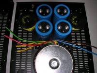
In my push-pull amps I build with CRC supply, with 44mF - 0.12R - 44mF. With my single ended amps I build with CLC supply, with 44mF - Hammond 159ZJ - 44mf.
The Hammond 159ZJ is 15mH 0.16R.
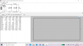
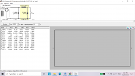
PSU Designer simulations show for CRC the ripple is around 70mV and for CLC the ripple was about 2mV. Results may vary depending on the capacitor ESR and current demand.
The CRC 70mV was for 2.6A. For 1.8A, the ripple was 50mA . For CLC, the ripple was also reduced, to around 1.3mV.
Of course these are simulation results but the real life results will be in the same range.
The Hammond 159ZJ is 15mH 0.16R.
PSU Designer simulations show for CRC the ripple is around 70mV and for CLC the ripple was about 2mV. Results may vary depending on the capacitor ESR and current demand.
The CRC 70mV was for 2.6A. For 1.8A, the ripple was 50mA . For CLC, the ripple was also reduced, to around 1.3mV.
Of course these are simulation results but the real life results will be in the same range.
Attachments
Yes, measuring the ripple is as simple as that. When I tried to measure ripple after the chokes were in I had a hard time getting the scope to trigger on the wave. Also had to go to my lowest setting on V/div.
The typical diyaudio store power supply board is fitted for parallel 0.47ohm resistors. I came across the recommendation to stay around the same 0.11 DCR as a group of four R on the board. There would be an increase in voltage drop but how much will the extra inductance add to the filtering potential?
Is there a practical limit to total inductance based on the current used by the supply? And how about amorphous core?
Cheers for that info.
I'll have to check my notes, but if I recall correctly from the modelling I've done in PSUD, simply moving from CRC to CLC is a more significant improvement re: ripple than is provided by increasing the inductance value after that. And that inductance increase usually has to be accompanied by an increase in resistance and physical size.
In my push-pull amps I build with CRC supply, with 44mF - 0.12R - 44mF. With my single ended amps I build with CLC supply, with 44mF - Hammond 159ZJ - 44mf.
The Hammond 159ZJ is 15mH 0.16R.
PSU Designer simulations show for CRC the ripple is around 70mV and for CLC the ripple was about 2mV. Results may vary depending on the capacitor ESR and current demand.
The CRC 70mV was for 2.6A. For 1.8A, the ripple was 50mA . For CLC, the ripple was also reduced, to around 1.3mV.
Of course these are simulation results but the real life results will be in the same range.
The Hammond chokes have a tolerance of 15% for both inductance & DCR. I'd be interested to know if you (or anyone else) have measured how close to spec yours are.
I haven't measured inductance and at such a low DCR a typical multimeter (I have cheap meters) will not measure accurately. Also to my knowledge the effective inductance will vary with current.
I think that the published specifications are close enough for the amplifiers that we build, and the difference in ripple from CRC to CLC is substantial.
I think that the published specifications are close enough for the amplifiers that we build, and the difference in ripple from CRC to CLC is substantial.
The inductance specified for the Hammond inductors is at the rated current. Hammond does state that the inductance may vary either way for current that differs from the specification.
The DC resistance may be measured with the help of a current source. I built a 1.0 Amp current source and verified the DC resistance of a pair 195T5 inductors were the specified 0.65 Ohms.
The DC resistance may be measured with the help of a current source. I built a 1.0 Amp current source and verified the DC resistance of a pair 195T5 inductors were the specified 0.65 Ohms.
Hello,
Going up with the mH value from 2/10 to 40/50 mH will surely change the sound but because if you dont try you will never know. It might even give you the possibility to lower the value of the first cap that stresses the transformer and the diodes a lot.
Greetings, Eduard
Going up with the mH value from 2/10 to 40/50 mH will surely change the sound but because if you dont try you will never know. It might even give you the possibility to lower the value of the first cap that stresses the transformer and the diodes a lot.
Greetings, Eduard
Hello,
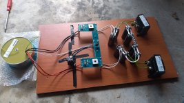
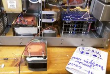
As you can see the proof of the pudding is in the eating.
Use of Lundahl chokes with a load around 1A ( a DDDAC with shunt supplies integrated on the boards) Chokes close to the actual circuit ( the biggest choke used as a choke input) and the DDDAC output transformers on the right side of boards.
Good luck with the 2 mH chokes.
Greetings, Eduard
Attachments
- Status
- This old topic is closed. If you want to reopen this topic, contact a moderator using the "Report Post" button.
- Home
- Amplifiers
- Pass Labs
- Hammond 159zl as clc choke