

I have built only the final stages, 2 stages per channel, to be driven by a differential Aikido tube stage. I was always looking for a Vertical stage in place of the Laterals used at Moskido. And this seems to be a great solution.
My problem is that the static current through each MOSfet is around 1,15A at 24V supplies and 1,3A at 30V supplies. The offset is quite stable after warming up to 55-58C and easily set after changing the P1 to 10kohms and R7 to 51kOhms.
Decreasing R13 and R14 to 0,33 would bring the current over 2,2 A, so probably I should rather increase R11.
The question is: should I aim to increase it more? Is it 1,2A enough considering a dual stage (so 2,4A in total per channel) driving 8Ohm speakers? Or will it leave the A class too early?
Thanks for your time to read my post and applologies if this is not a good thread for my questions!
The transformer specifications should say 2 X 20V AC at the secondaries... to begin with.
Some transformer manufacturers will let you specify the secondary voltage in 1V increments, so 2 x 21V AC might be perfect.
The voltage sag will also depend on the transformer VA rating; the higher the VA, the lesser of a sag.
I use 230V-specified transformers, at 2 X 20V AC, connected to 240V mains.... so that gives me around 2 X 21 V AC or so.
Of course, the quiescent current per each output transistor will also influence the whole thing.
It is also important to remember that mains voltage could vary substantially, depending on your electricity provider/distribution network. Just another factor to take into consideration.
There's a bit of a voltage drop across the thermistor as well.
Also, the power dissipation is directly proportional to (an increase) of supply voltage... so with 5U / cooler climates, it ain't gonna be a problem.
Last edited:
if you're content with sound , leave it
for gradual increase of Iq , try increasing resistor in series with opto-led
sensibly,please")
Thanks!
No extensive sound auditions yet, I have to build the solid state protection relay first and connect everything in the boxes; at the moment I am just testing the static and thermal parameters, to be sure they will survive.
I did some audition with them though directly from a headphone output to the power buffer and the sound seemed ok in my modest test speakers.
As all is done p2p It would be easier to replace the 0R47 resistors with 0R33 but I don't feel like it will be a good idea, so I will probably leave it as it is.
The transformer specifications should say 2 X 20V AC at the secondaries... to begin with.
Some transformer manufacturers will let you specify the secondary voltage in 1V increments, so 2 x 21V AC might be perfect.
The voltage sag will also depend on the transformer VA rating; the higher the VA, the lesser of a sag.
I use 230V-specified transformers, at 2 X 20V AC, connected to 240V mains.... so that gives me around 2 X 21 V AC or so.
Of course, the quiescent current per each output transistor will also influence the whole thing.
It is also important to remember that mains voltage could vary substantially, depending on your electricity provider/distribution network. Just another factor to take into consideration.
There's a bit of a voltage drop across the thermistor as well.
Also, the power dissipation is directly proportional to (an increase) of supply voltage... so with 5U / cooler climates, it ain't gonna be a problem.
I used a 2 x 18 volt 300 VA transformer. I thought the first watt power supply specified 18 volt. Does the M2 specify 20 volt?
The M2, with the standard input of 'K170 + 'J74 is good for a supply range of 21 to 24 Volts. The higher voltage should be used with caution when the JFets have an Idss greater than 8 mA. Power transformers with 18V or 19V secondaries are a good match.
The final supply voltage depends of the type of rectifier used, in addition to the transformer secondary voltage. The somewhat typical GCPC3502 blocks will drop about 3.5V to 3.8V under load. Other options are available that will drop less.
I initially used FEP30 diodes in the bridge rectifier PCBs that come with the store PSU boards. With an Antek AS-4218 and a set of 22,000 uF caps, I got +/– 22.2V on the amp PCBs. That is an improvement over the 3502 rectifiers, which would typically yield about 21.2V. More recently I switched to a pair of LT4320 based 'ideal' rectifiers, which increased the supply voltage to +/– 23.4V and also improved the sound of the amp.
Overall, I find that the quality of the PSU has a significant impact on the sound of an amplifier. Yes, even Class A amps depend on high quality PSUs.
Last edited:
I used a 2 x 18 volt 300 VA transformer. I thought the first watt power supply specified 18 volt. Does the M2 specify 20 volt?
If you go by specifications, then you'll get 21.2V, as you already mentioned. (I think Nelson used 300VA windings, on a 400VA core)
It appears that you want to go higher than that (21.2V, as I understand....) Power supply modifications will not get you there, you need to replace the transformer.
My previous post explains the most common factors in choosing the right transformer and the contributors that will affect the end result.
The main question you should be asking yourself is: "What am I trying to achieve?" Is it a hotter heatsink, more power, "better" sound...?
Some people want to measure 24V DC on rails, under the load, simply because the schematic reads: "24V"
You could increase the quiescent current, if the heatsinks are cool... that will give you a slight reduction in overall distortions, and hopefully a better sound than you'll be able to perceive as an improvement.
ACA builders reported an overall improvement in sound quality when they pushed ACA's from 24V to 30V... again, the idea sounds nice but this needs to be evaluated with (very) small ACA heatsinks in mind...
The best would be to get a 5A/30V dual rails laboratory power supply, signal generator, oscilloscope and the desired resistor value (similar to your speaker impedance...) at 50W or so dissipation. And then you can observe the onset of clipping vs. power supply rails relationship. Once happy with the result, just get the transformer that will give you a desired power supply rails' voltages
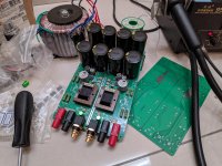
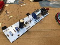
I am making myself a third M2 that having a more clean layout.
Because i dont have a good skill in wire management, so I sandwiched left, right, CRC, bridge rectifier, rca, banana into one board. And I am a happy kid now.
If any of you need the gerber files, I am happy enough to share here.
Because i dont have a good skill in wire management, so I sandwiched left, right, CRC, bridge rectifier, rca, banana into one board. And I am a happy kid now.
If any of you need the gerber files, I am happy enough to share here.
Attachments
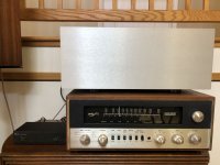
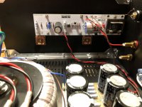
So I thought I should finally get around to posting about my M2 build. Huge thanks to Jim (6L6) for sending me a bunch of free parts (including those sweet PASS branded caps), and kickstarting this project. Also to TeaBag for the nice PCBs, which I also got from Jim's stash.
I'd done a bit of refurbishing work, like recapping the MAC1700 in the last photo, but this was my first "from-scratch" build. Also, electronics is a sizeable part of my work, so I didn't go into this completely clueless. In fact, I have some PCB designs for this amp mostly done, but I never pulled the trigger because of $$ (thanks again Jim for getting me started).
This ended up being a pretty vanilla build. I had hoped to build my own chassis, but that was going to be a huge amount of work for my first build... and not cheaper than the diyaudiostore/HiFi2000 chassis. I'm really happy with how it turned out though. Maybe one of these days I'll install some LEDs or a power switch on the front panel.
The transformer is from Antek. I started out with their 500VA trafo (because that's what they had in stock at the time), but the hum through my speakers was significant. If I held it outside the chassis as far away as the leads would allow, the hum became inaudible. I eventually got one of Antek's 400VA trafos with the static shield, and the hum improved quite a bit. It's definitely still present, but it doesn't interfere at listening distances. The mu metal shields around the input transformers don't seem to make much audible difference.
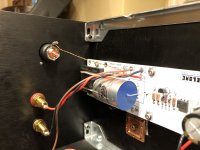
PS: +23.15V, -23.12V
DC Offset: <0.5mV on both channels
Input FETs have a high Idss (11.1mA) so I used 15R resistors for R3 and R4. They are operating at ~7.6mA bias and 54.5 deg C, which is good if a bit on the toasty side.
Musical Fidelity V90 DAC
MAC1700 preamp (I wired up some pre-outs for it)
KLH Model 20 Speakers (4 Ohm) that I found for free and refurbished
The sound is truly amazing. I can't believe how much music this amp pulls out of those relatively cheap speakers. I could listen all day.
I'd done a bit of refurbishing work, like recapping the MAC1700 in the last photo, but this was my first "from-scratch" build. Also, electronics is a sizeable part of my work, so I didn't go into this completely clueless. In fact, I have some PCB designs for this amp mostly done, but I never pulled the trigger because of $$ (thanks again Jim for getting me started).
This ended up being a pretty vanilla build. I had hoped to build my own chassis, but that was going to be a huge amount of work for my first build... and not cheaper than the diyaudiostore/HiFi2000 chassis. I'm really happy with how it turned out though. Maybe one of these days I'll install some LEDs or a power switch on the front panel.
The transformer is from Antek. I started out with their 500VA trafo (because that's what they had in stock at the time), but the hum through my speakers was significant. If I held it outside the chassis as far away as the leads would allow, the hum became inaudible. I eventually got one of Antek's 400VA trafos with the static shield, and the hum improved quite a bit. It's definitely still present, but it doesn't interfere at listening distances. The mu metal shields around the input transformers don't seem to make much audible difference.
PS: +23.15V, -23.12V
DC Offset: <0.5mV on both channels
Input FETs have a high Idss (11.1mA) so I used 15R resistors for R3 and R4. They are operating at ~7.6mA bias and 54.5 deg C, which is good if a bit on the toasty side.
Musical Fidelity V90 DAC
MAC1700 preamp (I wired up some pre-outs for it)
KLH Model 20 Speakers (4 Ohm) that I found for free and refurbished
The sound is truly amazing. I can't believe how much music this amp pulls out of those relatively cheap speakers. I could listen all day.
Attachments
Ohhh....I like those shiny Pass caps. Congratulations on your build!
Yes, that Jim is the Great Enabler.
Have you tried measuring the AC noise at the output with input shorted?
The spec for M2 has that at 500uV but the measurements I've seen
seems to be somewhat less than that.
Cheers,
Dennis
Yes, that Jim is the Great Enabler.
Have you tried measuring the AC noise at the output with input shorted?
The spec for M2 has that at 500uV but the measurements I've seen
seems to be somewhat less than that.
Cheers,
Dennis
Congratulations on your first build.
It looks very clean. I do have a few suggestions regarding the hum.
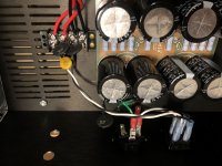
Try rotating the power transformer. My experience with Antek transformers is that it makes a difference. I have found that the best position is when the wire entry and exit points are aligned towards the front and back of the case.
Twist the power supply ground wire together with the V+ and V- all the way to the board V+ and V- connection, then continue the ground wire to the ground connection point.
Route the AC wires from the back of the case under the power supply board to the front of the case and provide connection to the transformer there. Move the rectifiers to between the transformer and power supply board.
Move the amplifier from the MAC1700. Perhaps the MAC1700 transformer is too close to the amplifier.
Here is something by diyAudio member Bonsai that has good information:
http://hifisonix.com/wordpress/wp-content/uploads/2019/02/Ground-Loops.pdf
Practical advice is towards the end of the article.
It looks very clean. I do have a few suggestions regarding the hum.
Try rotating the power transformer. My experience with Antek transformers is that it makes a difference. I have found that the best position is when the wire entry and exit points are aligned towards the front and back of the case.
Twist the power supply ground wire together with the V+ and V- all the way to the board V+ and V- connection, then continue the ground wire to the ground connection point.
Route the AC wires from the back of the case under the power supply board to the front of the case and provide connection to the transformer there. Move the rectifiers to between the transformer and power supply board.
Move the amplifier from the MAC1700. Perhaps the MAC1700 transformer is too close to the amplifier.
Here is something by diyAudio member Bonsai that has good information:
http://hifisonix.com/wordpress/wp-content/uploads/2019/02/Ground-Loops.pdf
Practical advice is towards the end of the article.
Congratulations on your first build.
It looks very clean. I do have a few suggestions regarding the hum.
Try rotating the power transformer. My experience with Antek transformers is that it makes a difference. I have found that the best position is when the wire entry and exit points are aligned towards the front and back of the case.
Twist the power supply ground wire together with the V+ and V- all the way to the board V+ and V- connection, then continue the ground wire to the ground connection point.
Route the AC wires from the back of the case under the power supply board to the front of the case and provide connection to the transformer there. Move the rectifiers to between the transformer and power supply board.
Move the amplifier from the MAC1700. Perhaps the MAC1700 transformer is too close to the amplifier.
Here is something by diyAudio member Bonsai that has good information:
http://hifisonix.com/wordpress/wp-content/uploads/2019/02/Ground-Loops.pdf
Practical advice is towards the end of the article.
All great suggestions, but this one is so important; however not that obvious:
"Move the amplifier from the MAC1700. Perhaps the MAC1700 transformer is too close to the amplifier."
It reminds me of the golden era of turntables... when people were struggling with how to eliminate hum, and at the end all that was required was to relocate the turntable from one side of the amplifier (cartridge very close to amps transformer), to the other side.
Thanks for the suggestions. There are a few new things I could try with regard to internal wiring. I did think of the proximity to the MAC1700, and it (surprisingly?) doesn't seem to make an audible difference. I think I have the Transformer rotated optimally. I could try putting it on it's side.
Really the thing that makes the all hum go away is more distance between the Transformer and everything else, but I'm confined to the chassis.
That said, I plugged it into my brother's JBL L100's, and they were silent with my ear right next to the drivers. Maybe it's because they are 8Ohm instead of 4? Or maybe there's something about the way everything was plugged into power?
Constant tinkering is the name of the game. I'm still loving this amp.
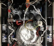
Hi all,
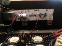
2 years after receiving all the pcbs and parts, I finally finished my M2.
Two problems:
The case (120mm tall) maybe too small to house the boiling mosfets. I will have to get a 200mm tall heat sink case.
The second problem: left channel has hum noise and volume is only half that of the right channel.
Right channel functions normally and sounds gorgeous. No hum.
Also the Problematic left side is 5C cooler than the right channel which is about 50C.
Where should I start to troubleshoot? Would it be cold solder?
(Photo shows M2 in progress)
Attachments
- Home
- Amplifiers
- Pass Labs
- Official M2 schematic