...............The sound is uninvolving though at the moment. ............
odd. Is your AC inlet filter a limitation?
OH - no buffer yet? That too!
")
That's the first time I've ever seen a thermal pad used between a GBPC packaged bridge rectifier, and the chassis!
If the M2's DC supply rails are ±23 volts, and if the M2 dissipates 160 watts of class-A power when no input signal is present,
then each rail delivers about 3.5 amperes. Math check: (3.5 * 23 * 2) = 161. Check.
The voltage drop across each of the two bridge rectifiers, is about 2.5 volts max. Datasheet says less, we round up for conservatism.
So the power dissipation of each of the two bridge rectifiers, is about (3.5 amps) times (2.5 volts) which equals about 9 watts. Needs heatsinking? Certainly. Needs thermal pad? Hmmm.
Fun fact: silicon diodes in a bridge rectifier, actually work better and better, the hotter you let them operate. As long as you stay below TjMax of course. Take a peek at the datasheet. Cowabunga!
Mark,
Ha ha! I praise your analysis of the situation. I can't say I was thinking quite so deeply about it. On the other had though, 9 watts is quite a lot of heat at a near point source. I generally like to keep things pleasantly warm, not hot. You have forgotten fault conditions in your analysis
Ha ha! I praise your analysis of the situation. I can't say I was thinking quite so deeply about it. On the other had though, 9 watts is quite a lot of heat at a near point source. I generally like to keep things pleasantly warm, not hot. You have forgotten fault conditions in your analysis
Finally bringing up my M2 implementation... as you can see, Tea Bag PCBs. A very nice solid product if you are reading. A DIY aluminium chassis (slots all millled with hand router!). 300VA transformer and some nice big sinks from RS - 177AB1500B @ 0.23C/W. Tea Bag BOM. PSU hardwired under proto board with 2mm^2 tinned copper wire.
Anyway, biasing no problems using increased value of R7 as per Tea Bag. Both outputs within 5mV of 0V DC. Tiny amount of hum, volume control independent.
Driving via B1 buffer unmodified. No JFETs at input to M2 - wired straight into Edcor. 1st surprise... huge reduction in volume compared to my ACAs. Mmm.. I figure that's the 1K resistor on output of B1 driving about 600R. I forgot about the 600R vs 6K input impedance thing! Will get rid of that 1K tomorrow as per Zen Mod suggestion. The sound is uninvolving though at the moment. Big suckage in evidence maybe? Hopefully better things to come.
Several of us, Teabag included had less than stellar results upon fire up. Let it play, if all is well it will sound wonderful a little later.
Russellc
No need for pads under rectifiers, likely no help anyway, and may even hinder heat dissipation? Pads are to electrically insulate devices that need to be isolated from what they are attached to. Some transfer heat better than others. No need here, right?
Russellc
Russellc
Last edited:
Russellc,
Thanks for reminding me about the initial expectations. I have binned the 1K at the output of the B1 and that has made a huge difference. It does sound impressive now. Very textured and refined on the chamber music I was listening to. Maybe I will get further improvements with burn-in.
PS The pads are Keratherm Red. Just about the best heat transfer pad you are going to get, and much better than metal on metal. They sell 'em on the store. I think you will find that a metal on metal contact is not nearly as good. From RS...
Thermal transfer pads are used to improve the heat transfer capability between two surfaces... Thermal transfer pads are installed between the solid state relay or other component and the heatsink surface. The pads are designed to cover up the entire mating area between the heatsink and the solid state relay, leaving no air gaps, voids, run-out or build-up.
Last edited:
Put a pad under one bridge rectifier and no pad under the other. Run the M2 for two hours and take a temperature measurement of each bridge rectifier using a no contact infrared thermometer. Now that you see the temperatures, which thermal contact method do you prefer? Make two of those.
Google Image
Google Image
Quite. That is what you would need to do. I don't have that equipment. But I would expect the rectifier with thermal pad to be cooler; otherwise thermal transfer pads are badly named! Of course, the pad should improve the reliability of thermal transfer with less than exactly planar mating surfaces and other surface imperfections. Have you done that type of experiment?
Russellc,
Thanks for reminding me about the initial expectations. I have binned the 1K at the output of the B1 and that has made a huge difference. It does sound impressive now. Very textured and refined on the chamber music I was listening to. Maybe I will get further improvements with burn-in.
PS The pads are Keratherm Red. Just about the best heat transfer pad you are going to get, and much better than metal on metal. They sell 'em on the store. I think you will find that a metal on metal contact is not nearly as good. From RS...
I use Keratherm extensively and have for years, since initial F5 days. Seems like a waste of keratherm, but who am I to complain? Never blown one yet. I have used separate Diodes, 8 per channel to make bridges (dual mono F5) and those did need to be insulated, and keratherm was used. I find it hard to believe even keratherm would transfer heat to metal than bare, or bare with goop, which is standard device to heat sink protocol where electrical isolation would not be required.
As Zenmod has said, you can make your nikes x-ray proof, but why? As long as you are pleased and it is working, win-win!!! Glad you are enjoying your M2, a wonderful amp!
Russellc
Last edited:
Quite. That is what you would need to do. I don't have that equipment. But I would expect the rectifier with thermal pad to be cooler; otherwise thermal transfer pads are badly named! Of course, the pad should improve the reliability of thermal transfer with less than exactly planar mating surfaces and other surface imperfections. Have you done that type of experiment?
Again, thermal transfer is not chief job for pad, electrical isolation is. They are a necessary evil. fortunately, some pads transfer better than others. I guess an experiment could be fashioned where a very very (Crickey hot) surface is utilized. I sure as heck would rather touch it with the protection of a keratherm than without, no? LOL just jacking with you! Now go build Aleph J...if you like M2, you will like it too!!!
Again, thermal transfer is not chief job for pad, electrical isolation is.
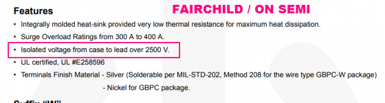
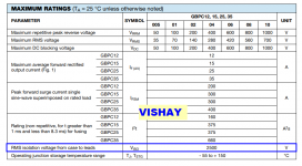
Not in a GBPC packaged bridge rectifier.
The package is electrically isolated from the four pins of the bridge. Datasheet snippets below. They guarantee you can apply 2499 volts between package and pin, and no current will flow. There is no need for an additional insulator between bridge and chassis or heatsink.
_
Attachments
Not in a GBPC packaged bridge rectifier.
The package is electrically isolated from the four pins of the bridge. Datasheet snippets below. They guarantee you can apply 2499 volts between package and pin, and no current will flow. There is no need for an additional insulator between bridge and chassis or heatsink.
_
My point precisely. Unlike the devices I used on my F5, These rectifier blockss require no electrical isolation, which is the point of the pads, no?
While the block devices could use some heat to be transferred away from them, I think just bolting them to the case is sufficient, (at least it has been for everyone here previously) and think the adding of a pad isnt going to help what heat transfer is useful.
Russellc
Last edited:
RussellC, MJ,
Thanks for your good wishes and discussion. You have bought me to 60% certain of my ground. See Wikipedia "Thermally conductive pad" though!. I leave it there. I will try that experiment one day. I'm sure you are right on one thing though (well, most things probably) - it's belt and braces in this application.
Thanks for your good wishes and discussion. You have bought me to 60% certain of my ground. See Wikipedia "Thermally conductive pad" though!. I leave it there. I will try that experiment one day. I'm sure you are right on one thing though (well, most things probably) - it's belt and braces in this application.
This discussion makes me chuckle and reminds me of a post by Mark a week or so ago: https://www.diyaudio.com/forums/pass-labs/327746-h2-9.html#post5563071
Bravo. You're right! Funny. And reading that H2 thread reminds me of when I was at university 30 years ago. I had just listened to pair of Quad II's for the first time at another student's digs which was fantastic. He had built his own preamp and was obsessing about capacitors which I thought seemed a bit odd. I spoke to a dear old lecturer of about 75yrs old in the morning who used to knock around the labs chatting to the students. He laughed about the concept of still using valves. He said that they start deteriorating the second you turn them on, and much better to make a decent transistor amp and create a second harmonic generator, which he said was easy. That chat is so clear in my memory!
FYI From AMD online document Thermal Interface Material Comparison: Thermal Pads vs. Thermal Grease
The key feature of thermal pads is their ability to change their physical characteristics. At room temperature these materials are firm and easy to handle. This allows more control when applying the solid pads to a heatsink surface. The thermal material softens as it reaches component operating temperatures. With the heat from the operating processor and a light clamping pressure, the phase-change material readily conforms to both surfaces. This ability to completely fill the interfacial air gaps and surface voids that are typical between component packages and heatsinks allows performance comparable to thermal grease.
I'm having some difficulty with my 3rd M2 build. The right channel seems to work just fine. But as I bring the left channel up it seems fine at first, I can adjust for DC offset, then seconds later both source resisters get very hot (I mean burn your fingers hot). I've pulled the boards off the heatsinks to look everything over, but all checks out...resistor values, transistors correct and orientated properly, capacitors are fine, I just can't figure it out. One thing I did notice when I released the mosfets from the sinks, it looks like I over torqued the screws and really compressed the thermal pads (maybe to the point they could conduct?) Let me know if you have any suggestions. Thanks


Resistors too hot suggests a failure of the optocoupler negative feedback loop which regulates bias. I'd look for open circuits in the R10, R11, R12, Q5 current loop. I'd pry the 4N35 DIP out of its socket, straighten its pins, and very very carefully reseat it, making sure all six pins go where they're supposed to. BTW if Q6 or Q7 became shorted, that would play hell with the bias loop too.
You could temporarily remove the 0R47 source resistors and replace them with 47R resistors for debug purposes. Now you can run the amp all by itself on the bench, without a heatsink, and attach probes to your heart's content.
You could temporarily remove the 0R47 source resistors and replace them with 47R resistors for debug purposes. Now you can run the amp all by itself on the bench, without a heatsink, and attach probes to your heart's content.
- Home
- Amplifiers
- Pass Labs
- Official M2 schematic