This was my understanding as well, it is certainly easy enough to replace or bypass that big PIO cap. Just trying an experiment to see how different things sound. Need to finish the rest of the chassis so it becomes more portable.
Congratulations Eric
")
Experimentation is the way to go and get audio satisfaction.
See my M2 prototype Official M2 schematic
Yellow 2,2 uF industrial Marcon brand was the winner for 3300 uF decoupling
Can I use the the AnTek 400VA 20 + 20 transformer? I’m going to use the DIYA power supply.
Yes, I have done it many times in FW clones when Antek was out of 18V.
@Eric,
great to see something homemade again.
I will adopt the idea with the 20R Trimpot if i may.
From my experience I would recommend some
less heat conducting material for your cap-lifter.
My M2 runs at about 50°C (heatsink) and even the
frontpanel gets mighty warm after an hour.
cheers
A.
great to see something homemade again.
I will adopt the idea with the 20R Trimpot if i may.
From my experience I would recommend some
less heat conducting material for your cap-lifter.
My M2 runs at about 50°C (heatsink) and even the
frontpanel gets mighty warm after an hour.
cheers
A.
Pass DIY Addict
Joined 2000
Paid Member
Attila: I was looking for something that would be less heat conducting to put some space between the sink and the caps. I didn't think plastic or wood would last as long as metal, so I chose the metal band. It will certainly carry some heat, but I was hoping that with a little air flow through the chassis they would stay a little cooler than the sink temps.
I also have a few caps to experiment with. Since my other amps feature more "audiophile" grade parts, I figured I'd play with the PIOs here. I'll a bit more interested in playing around with the sound this time rather than trying to achieve the most "accurate/etc" sound. It's kind of a warm-up act for the 300B I plan to build next year.
I'll post a few more images when the chassis is completed. Need to order a new set of RCAs and some speaker terminals. A few years ago I purchased a ton of RCA inputs from China and the barrel on *ALL* of them is about 0.5mm too small, thus standard RCA cables don't connect well. Live and learn...
That 600:20K transformer has a turns ratio of 1.0 :: 5.77 and so, following the arithmetic in this M2 thread, the transformer primary presents a load of (23500 / (6.77 * 6.77)) = 512 ohms to the dual JFET input stage. I.e. the input stage is driving a 512 ohm load (!) That's working the JFETs awfully doggone hard, especially at max input level.
I don't know about the Chinese transformer, but the two Edcor transformers I measured had a DC resistance of 44 ohms in their primary ("600 ohm") windings. 10 millivolts of DC offset from the JFET input stage, into a 44 ohm DC resistance, results in a DC magnetizing current of 0.23 milliamps in the primary (Ohm's Law). Enough DC current to make me, very uncomfortable.
I just measured and the primary DC resistance of the primary is about 86 ohms.
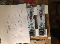
M2 Clone - Tea-bag pcbs.
Getting there
4Ux300 case will be cramped but probably doable (bottom plate and sink on picture from 2U case to test fit). It would be nice to have predrilled 400 deep 3U or 4U heatsinks. The 5Ux400 is to big for my taste - until the 100W class -A fever hits me
Getting there
4Ux300 case will be cramped but probably doable (bottom plate and sink on picture from 2U case to test fit). It would be nice to have predrilled 400 deep 3U or 4U heatsinks. The 5Ux400 is to big for my taste - until the 100W class -A fever hits me
Attachments
Getting there
4Ux300 case will be cramped but probably doable (bottom plate and sink on picture from 2U case to test fit). It would be nice to have predrilled 400 deep 3U or 4U heatsinks. The 5Ux400 is to big for my taste - until the 100W class -A fever hits me
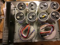
Would you please tell us where did you get those capacitors.
kbergsson, that looks exactly like what im planning for my M2. I also just got hold of some 47mF/63V PEH caps so will go for dual mono. I am a bit worried about noise radiated from the transformers being picked up by the Edcors though, as i seem to have a bit of that in my F6 in the 4U chassis (not dual mono but 400VA transformer).
Let us know it gets on!
Let us know it gets on!
Silasmellor I have the Diyaudio powersupply solution (8x 18000uf) in my F6 and unshielded 400VA trafo. Had some supply noise at first then remembered to do grounding excactly as 6L6s F6 build guide. My F6s are now totally silent on my 100+db Altecs.
Did you get your Kemets from surplus in Holland? I got mine there (tunasto) for a good price. Jonny Canuck, correkt 47000uf long life PEH200. Mouser has them as well but they are expensive. Mine are as said from surplus but according to datecodes all between 2 and 3 years old, seem to be unused.
I have some screens for the edcors on the way, if necessary, but they will be placed furthest from the trafos.
Last edited:
Yes, I saw the link to that surplus store in another thread and snatched up some of those caps there as well. They are in mint condition, so a very nice find! How do you plan to connect them? I am thInking to use a dual 300va, 19v secondaries, and use 4x2 ohm (5w) between cap banks to bring ripple down further. Psud2 says that should give around 23v after the last caps.
I also use the grounding scheme from the guide. From psu board, via cl60 To chassis. Each amp board connected to +/-/gnd.. The noise is very faint with me ear next to the woofer, but I can see higher order harmonics in the fft which bother me (though i am not sure they are audible). I’m not sure if it is radiated noise from the transformer getting into the Jensen’s, but that’s currently my hypothesis.
Looking forward to more pictures, my build is still some way off, so I am curious how this works out (great I am sure).
It will be similar to your plans i.e. I have some 0R1 10w wirewounds as R in CRC, so 47000uf-0R1-47000uf and maybe 10uf large Wima as bypass per rail. The trafos I got are 2x 300VA dual 18V seconaries. I dont have any simulation sw. So If I like the sound is will be ok, If not Ill have to try something else
In the F6 I use shielded input cable with shield connected to gnd cable at input connector. I have used Tubes for a long time so if I dont hear noise I dont care
It will take some time to finish as I have not bought a chassis yet, and dont want to dissassemble my F6 to test the M2. I like the F6 to much
The store is Electrodump.nl i think.
Yes, I saw the link to that surplus store in another thread and snatched up some of those caps there as well. They are in mint condition, so a very nice find! How do you plan to connect them? I am thInking to use a dual 300va, 19v secondaries, and use 4x2 ohm (5w) between cap banks to bring ripple down further. Psud2 says that should give around 23v after the last caps.
I also use the grounding scheme from the guide. From psu board, via cl60 To chassis. Each amp board connected to +/-/gnd.. The noise is very faint with me ear next to the woofer, but I can see higher order harmonics in the fft which bother me (though i am not sure they are audible). I’m not sure if it is radiated noise from the transformer getting into the Jensen’s, but that’s currently my hypothesis.
Looking forward to more pictures, my build is still some way off, so I am curious how this works out (great I am sure).
Last edited:
Get the most out of M2/F6
Had some time to listen to M2 amplifier I build few weeks ago. Soft low end, soft on top. I like the soft low end, but not the lack of details in music. When listening to music the lack of details is very obvious at some songs, however still something special, a bit like water color.
I am using allready transformers (jensen ground isolator) to avoid hum (cause by TV, SAT antenna) in my TV setup. To reduce sound impact of transformer I have placed the passive volume attenuator behind the transformer.
This reduces the THD&N at low freqencies for example by 14db (0db compared to -40db signal level according to jensen datasheets). Also the micro details in music are not lost and setup is more immune to inducted distortion by electric fields.
To get the most out of M2 and F6 I would like to place the volume attenautor also behind jensen / edcor transformers. For M2 this would be possible I guess. Could you help please if this would be feasible and what pot/relay volume attenuator impendance would fit best to match output impedance of transformer and the power transistors.
Any chance to put a dual volume control behind the jensen transformer in a F6? I do not know where to place.
Attachments
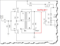
The traditional position for a volume control would be "R2". Use a 100K pot to ground, input comes from R1, wiper goes to Q3 and Q4. Since it's DC coupled, if the input signal happens to have any DC offset, changing the volume control can produce a scratchy sound.
You probably don't want to drive the output stage from an impedance that varies with volume control setting. So you probably don't want to install the pot between the secondary and the output stage.
You probably don't want to drive the output stage from an impedance that varies with volume control setting. So you probably don't want to install the pot between the secondary and the output stage.
Last edited:
Had some time to listen to M2 amplifier I build few weeks ago. Soft low end, soft on top. I like the soft low end, but not the lack of details in music. When listening to music the lack of details is very obvious at some songs, however still something special, a bit like water color.
I am using allready transformers (jensen ground isolator) to avoid hum (cause by TV, SAT antenna) in my TV setup. To reduce sound impact of transformer I have placed the passive volume attenuator behind the transformer.
This reduces the THD&N at low freqencies for example by 14db (0db compared to -40db signal level according to jensen datasheets). Also the micro details in music are not lost and setup is more immune to inducted distortion by electric fields.
To get the most out of M2 and F6 I would like to place the volume attenautor also behind jensen / edcor transformers. For M2 this would be possible I guess. Could you help please if this would be feasible and what pot/relay volume attenuator impendance would fit best to match output impedance of transformer and the power transistors.
Any chance to put a dual volume control behind the jensen transformer in a F6? I do not know where to place.
Odd, I note none of the soft low end or lack of detail.... I guess rooms, ancillaries, and speakers can change things up?
- Home
- Amplifiers
- Pass Labs
- Official M2 schematic