I have attached a pic of the brackets. These are standard brackets from hardware store and measure 105x105x90x3mm. One end needs to be cutted with an angle grinder and I had to drill some additional holes for mouning on the baseplate. I have ordered also L-Brackets from Audiophonics : Achats de Produits Hi-Fi Audio Electroniques et DIY - Audiophonics. But these are made of only 1.4mm thin aluminium and have a bulge which is not necessary for potted transformers. You can see one in the background of attached pic.Wow thats impressive! Some nice details there, I also like the rectifiers mounted on the faceplate. What l bracket did you use for the transformer?
Yes I really like their transformers. I used a 2x20, 300VA in a recent build but didn’t realize I’d have to mount it vertically to fit the chassis. I had a friend weld L brackets to the mounting plate so was curious how much extra space the 400VA would take for future builds.
Same happend to me. I have allready a Dissipante enclosure with a 400mm depth and believed the Deluxe 4U would be also 400mm. Had ordered therefor the toriody transformer with a baseplate for horizontal mounting.
 I have used the transformer baseplate as additional shielding and mounted it on the L-Bracket. Plan 75mm of space for the vertical mounted transformer including bracket.
1543, nicely done!
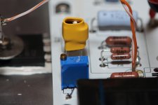
That pretty transformer shield could start a fad! So... 117,500uF + 220,000uF PER RAIL in psu filter capacitance, is that right? It sure looks cool. May I ask what inductance you're using in there?
I like the look of the polished transformer shield too. Damned that there is no acrylic cover or frontplate so that I can see it all the time
The caps are 4,700µF each, so 24 x 4,700 = 112,800 per rail + 48 x 4,700 = 225,600 per rail after DC choke.
Inductance of TRIAD C-59U chokes is 10mH. For an M2 the CLC PSU is oversized. The sonics are mainly influenced by edcor transformer. I guess a FW standard supply will not sound any different.
Attachments
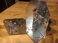
I have attached a pic of the brackets. These are standard brackets from hardware store and measure 105x105x90x3mm. One end needs to be cutted with an angle grinder and I had to drill some additional holes for mouning on the baseplate. I have ordered also L-Brackets from Audiophonics : Achats de Produits Hi-Fi Audio Electroniques et DIY - Audiophonics. But these are made of only 1.4mm thin aluminium and have a bulge which is not necessary for potted transformers. You can see one in the background of attached pic.
Same happend to me. I have allready a Dissipante enclosure with a 400mm depth and believed the Deluxe 4U would be also 400mm. Had ordered therefor the toriody transformer with a baseplate for horizontal mounting.
I like the look of the polished transformer shield too. Damned that there is no acrylic cover or frontplate so that I can see it all the time
The caps are 4,700µF each, so 24 x 4,700 = 112,800 per rail + 48 x 4,700 = 225,600 per rail after DC choke.
Inductance of TRIAD C-59U chokes is 10mH. For an M2 the CLC PSU is oversized. The sonics are mainly influenced by edcor transformer. I guess a FW standard supply will not sound any different.
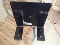
Ah I see. This is what I had to with the mounting plate.
Attachments
Ah I see. This is what I had to with the mounting plate.
Your version is perfect. Well done. Originally I thought about getting a bracket bended according to drawing. But to use the original plate for welding would be even better and cheaper. Or for free if you have a friend who can do the welding.
Your version is perfect. Well done. Originally I thought about getting a bracket bended according to drawing. But to use the original plate for welding would be even better and cheaper. Or for free if you have a friend who can do the welding.
The welding was free and the brackets were $14
4 Pack 4Lx3H Handcrafted Forged Rustic Reclaimed
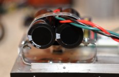
Who is the manufacturer of the yellow colored 600:20K transformers, in photo 4 of post #2697? Does their sonic character duplicate that of the Edcor 600:15K transformers in the original M2?
I second the question
(did I miss the answer?)
It was very expensive for me to ship the Edcor transformer from the USA. Mine was sourced from a Chinese supplier. Here is the link. It sounded good but does not like any bit of DC voltage at the input at all. Any DC (>10mV) will cause distortion. I had to match input JFET very well for least DC offset. Physically smaller than the Edcor. Dont have the Edcor to compare at the moment. Will try and compare in future when I do get hold of the Edcor.
商品详情
商品详情
That 600:20K transformer has a turns ratio of 1.0 :: 5.77 and so, following the arithmetic in this M2 thread, the transformer primary presents a load of (23500 / (6.77 * 6.77)) = 512 ohms to the dual JFET input stage. I.e. the input stage is driving a 512 ohm load (!) That's working the JFETs awfully doggone hard, especially at max input level.
I don't know about the Chinese transformer, but the two Edcor transformers I measured had a DC resistance of 44 ohms in their primary ("600 ohm") windings. 10 millivolts of DC offset from the JFET input stage, into a 44 ohm DC resistance, results in a DC magnetizing current of 0.23 milliamps in the primary (Ohm's Law). Enough DC current to make me, very uncomfortable.
I don't know about the Chinese transformer, but the two Edcor transformers I measured had a DC resistance of 44 ohms in their primary ("600 ohm") windings. 10 millivolts of DC offset from the JFET input stage, into a 44 ohm DC resistance, results in a DC magnetizing current of 0.23 milliamps in the primary (Ohm's Law). Enough DC current to make me, very uncomfortable.
Would the M2 work with a tube preamp with 20db gain? I’m trying to decide between the M2 and F4.
What's the sensitivity of the speakers they will be driving?
I'm driving an M2 with a tube amp of about 20 dB of gain. This set up drives speakers with a sensitivity of 91 dB. It works great!
I've had an F4 as well...in fact I repurposed the chassis and power supply of the F4 and made it an M2.
ZM says we're not allowed to compare the two
...but I prefer the M2.
Last edited:
That 600:20K transformer has a turns ratio of 1.0 :: 5.77 and so, following the arithmetic in this M2 thread, the transformer primary presents a load of (23500 / (6.77 * 6.77)) = 512 ohms to the dual JFET input stage. I.e. the input stage is driving a 512 ohm load (!) That's working the JFETs awfully doggone hard, especially at max input level.
I don't know about the Chinese transformer, but the two Edcor transformers I measured had a DC resistance of 44 ohms in their primary ("600 ohm") windings. 10 millivolts of DC offset from the JFET input stage, into a 44 ohm DC resistance, results in a DC magnetizing current of 0.23 milliamps in the primary (Ohm's Law). Enough DC current to make me, very uncomfortable.
Dear Mark, I did not measure the DC resistance but your observation is probably right as I reported earlier about the DC sensitivity. Let me make a measurement tonight and report.
Pass DIY Addict
Joined 2000
Paid Member
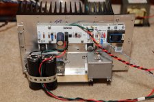
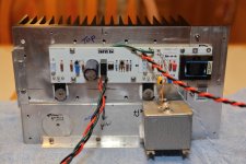
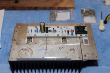
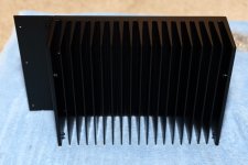
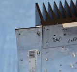
I've been working on my M2 for a little while now and still have a little bit to go. I've designed it in a "modular" fashion, with an outboard power supply that can also be used with my F4 and (not yet built) Aleph-J. I started with a 9x13" heatsink that I found at the flea market for $6. I had someone at the university product development lab cut it in half for me and I gave it light coat of black paint.
Because the sink wasn't wide enough to accommodate the circuit board with the mosfets placed in ideal locations for heat dissipation, I attached a 1/2" aluminum L-bracket and a 1/8" x 2" strip of aluminum bar to one side.
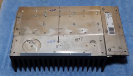
I used Tea-Bag's boards along with the Harris 9240, so I had to make R6 47k5 and R7 53k in order to achieve 0mV across speaker terminals. PSU rails are plus/minus 22.6v and I measure 0.594v across R13 and R14. With stock configuration, this works out to 1.26A bias or 58w per channel. The sinks provide a 20c rise over ambient temperature. I used some mica and goop to mount the mosfets, they get about 10c hotter than the sink itself.
I used a 20R multiturn pot in place of R3/R4. I used my most mis-matched jFets (10.66mA 2SK170 and 6.90mA 2SJ74) and the 20R allows me to balance the output of the buffer with precision. I slathered the jFets with some heatsink grease and wrapped them with heat shrink tube. For C2, I used a NOS Russian PIO 10uF MBGCh cap - thought it would "fit" better with the "tube" sort of flavor of this amp.
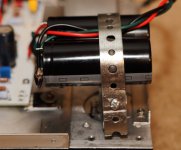
I used some steel banding with a bit of rubber padding to make a clamp to hold the local power supply caps (39,000uF each) to the sinks. This arrangement holds them tightly, but isolates them a bit from the heat of the sink. The outboard PSU will have another bank of caps and about 0R1 resistors, followed by the power umbilical, thus forming a CRC filter.
I'll use some figured maple for the front and top of the chassis. Just a bit more structural work to go then I'll move it into my main system for some listening.
Because the sink wasn't wide enough to accommodate the circuit board with the mosfets placed in ideal locations for heat dissipation, I attached a 1/2" aluminum L-bracket and a 1/8" x 2" strip of aluminum bar to one side.
I used Tea-Bag's boards along with the Harris 9240, so I had to make R6 47k5 and R7 53k in order to achieve 0mV across speaker terminals. PSU rails are plus/minus 22.6v and I measure 0.594v across R13 and R14. With stock configuration, this works out to 1.26A bias or 58w per channel. The sinks provide a 20c rise over ambient temperature. I used some mica and goop to mount the mosfets, they get about 10c hotter than the sink itself.
I used a 20R multiturn pot in place of R3/R4. I used my most mis-matched jFets (10.66mA 2SK170 and 6.90mA 2SJ74) and the 20R allows me to balance the output of the buffer with precision. I slathered the jFets with some heatsink grease and wrapped them with heat shrink tube. For C2, I used a NOS Russian PIO 10uF MBGCh cap - thought it would "fit" better with the "tube" sort of flavor of this amp.
I used some steel banding with a bit of rubber padding to make a clamp to hold the local power supply caps (39,000uF each) to the sinks. This arrangement holds them tightly, but isolates them a bit from the heat of the sink. The outboard PSU will have another bank of caps and about 0R1 resistors, followed by the power umbilical, thus forming a CRC filter.
I'll use some figured maple for the front and top of the chassis. Just a bit more structural work to go then I'll move it into my main system for some listening.
Attachments
-
 IMG_1435.JPG173.7 KB · Views: 404
 -
 IMG_1434.JPG284.1 KB · Views: 402
 -
 IMG_1430.JPG189.1 KB · Views: 409
 -
 IMG_1429.JPG270.6 KB · Views: 759
 -
 IMG_1236.JPG238.2 KB · Views: 750
 -
 IMG_1235.JPG190 KB · Views: 860
 -
 IMG_1234.JPG115.3 KB · Views: 877
 -
 IMG_1233.JPG269.7 KB · Views: 881
 -
 IMG_1436.JPG183.2 KB · Views: 319
Its uniquely yours! Congratulations.I've been working on my M2 for a little while now and still have a little bit to go. I've designed it in a "modular" fashion, with an outboard power supply that can also be used with my F4 and (not yet built) Aleph-J. I started with a 9x13" heatsink that I found at the flea market for $6. I had someone at the university product development lab cut it in half for me and I gave it light coat of black paint.
Because the sink wasn't wide enough to accommodate the circuit board with the mosfets placed in ideal locations for heat dissipation, I attached a 1/2" aluminum L-bracket and a 1/8" x 2" strip of aluminum bar to one side.
I used Tea-Bag's boards along with the Harris 9240, so I had to make R6 47k5 and R7 53k in order to achieve 0mV across speaker terminals. PSU rails are plus/minus 22.6v and I measure 0.594v across R13 and R14. With stock configuration, this works out to 1.26A bias or 58w per channel. The sinks provide a 20c rise over ambient temperature. I used some mica and goop to mount the mosfets, they get about 10c hotter than the sink itself.
I used a 20R multiturn pot in place of R3/R4. I used my most mis-matched jFets (10.66mA 2SK170 and 6.90mA 2SJ74) and the 20R allows me to balance the output of the buffer with precision. I slathered the jFets with some heatsink grease and wrapped them with heat shrink tube. For C2, I used a NOS Russian PIO 10uF MBGCh cap - thought it would "fit" better with the "tube" sort of flavor of this amp.
I used some steel banding with a bit of rubber padding to make a clamp to hold the local power supply caps (39,000uF each) to the sinks. This arrangement holds them tightly, but isolates them a bit from the heat of the sink. The outboard PSU will have another bank of caps and about 0R1 resistors, followed by the power umbilical, thus forming a CRC filter.
I'll use some figured maple for the front and top of the chassis. Just a bit more structural work to go then I'll move it into my main system for some listening.
That 600:20K transformer has a turns ratio of 1.0 :: 5.77 and so, following the arithmetic in this M2 thread, the transformer primary presents a load of (23500 / (6.77 * 6.77)) = 512 ohms to the dual JFET input stage. I.e. the input stage is driving a 512 ohm load (!) That's working the JFETs awfully doggone hard, especially at max input level.
I don't know about the Chinese transformer, but the two Edcor transformers I measured had a DC resistance of 44 ohms in their primary ("600 ohm") windings. 10 millivolts of DC offset from the JFET input stage, into a 44 ohm DC resistance, results in a DC magnetizing current of 0.23 milliamps in the primary (Ohm's Law). Enough DC current to make me, very uncomfortable.
I just checked the m2 schematics posted by Mr. Pass; it seems that, with a properly matched Q3/Q4, the common point between R3&R4 should be sitting at 0V DC with a symmetrical power supply; hence no current should be running through the primary. Any current running through the primary would disturb (deduct from) the quiescent current running through the Q3&Q4...
Pass DIY Addict
Joined 2000
Paid Member
just put something to bypass that PIO, for starters
I love them , but they tend to err on sirupy side ....... together with xformer , it can be too much ..... so , trying later some other type of cap could be wise
This was my understanding as well, it is certainly easy enough to replace or bypass that big PIO cap. Just trying an experiment to see how different things sound. Need to finish the rest of the chassis so it becomes more portable.
- Home
- Amplifiers
- Pass Labs
- Official M2 schematic