... my try this sunday...
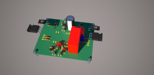
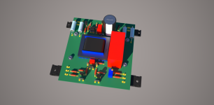
I will go with vertically mounted PCB (FET´s directly screwed onto heatsink): needs new symbols for this kind of mounting.
What do you use for the PASS typically 3W resistors? Should place two parallel, parallel to MP´s on PCB.
That´s all for the weekend... finishing to listen to Yes - Starship Trooper - 24bit/192kHZ - ifi DAC - custom tube headphone amplifier - HD600 - HQPlayer.
Jean-Paul
Attachments
Jean-Paul,
This is the resistor used in several First Watt amplifiers that had inside pictures published.
ERX-3SJR47 Panasonic Electronic Components | P0.47W-3BK-ND | DigiKey
Here is a review of the First Watt M2 on 6Moons.com
6moons audio reviews: FirstWatt M2
To get more people interested in your boards you might want do make them compliant with the "Universal PCB & Semiconductor Mounting Specification (UMS)" published on the DIYAudioStore site. To see the diagram go to http://www.diyaudio.com/store/ select Chassis and you will find the link in the Technical Information section.
Last edited:
What do you use for the PASS typically 3W resistors? Should place two parallel, parallel to MP´s on PCB.
Jean-Paul
You don't need to parallel but having that option on the pcb is an extremely nice feature for tweaking purposes.
Thanks for sharing this design with us Mr. Pass. I have noticed over the past few years a lot of your designs have utilized a transformer within the circuit. This seems to me like a departure from some of your earlier designs. I'm curious if this is something you have started doing because the way you design amps have evolved or could it be said that there are many ways to build an amp and that you have just been exploring the avenues that transformers open up? Either way your contribution to open source hardware is truly commendable and I deeply appreciate it.
Just playing.

It is keeping you young looking!
I thought I would blow some smoke this morning.
Do you think the input transformers in the F6 contribute to the excellent sound stage of this amp or is it the circuitry itself or possible a combination of both?
Last edited:
... UMS F-5x template...
Jean-Paul
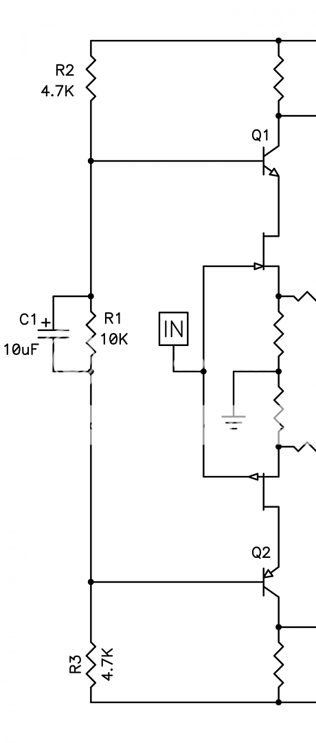
Do you have a schematic?
- Home
- Amplifiers
- Pass Labs
- Official M2 schematic