No, you are talking about two different issues a strain gauge might very well be a perfect displacement transducer but LP's have been equalized for ideal velocity sensitive transducers of which most cartridges are not due to several factors. There is no way the frequency response is correct without de-emphasis of some kind.
I think this is correct http://www.diyaudio.com/forums/analogue-source/211081-strain-gauge-jfet-pre-amp.html#post2992786 .
The deviation is 12 dB for frequencies above 2.122kHz.
I'd seriously consider using Pearl 2. It already has the RIAA correction figured out.
Here is the link to the article
https://www.passdiy.com/project/preamplifiers/pearl-2
Here is the link to the article
https://www.passdiy.com/project/preamplifiers/pearl-2
Pearl for strain gauge
You will have to adapt the eq of the Pearl to the strain gauge.
I found this blog about equalizing strain gauge cartridges. Audio Investigations: Equalizing the strain gauge
You will have to adapt the eq of the Pearl to the strain gauge.
I found this blog about equalizing strain gauge cartridges. Audio Investigations: Equalizing the strain gauge
Would digital equalisation be considered evil for this application?
This would be trivial with less dynamic range issues than digital RIAA (which IMHO are overstated).
I changed the approach a little. I thought first the LSK would be a nice circuit to start from, as an added benefit I could play in the Pass-Labs forum with all the nice people. But when searching for other PCBs at ebay I came across one of the JC-2 clones made in China. The John Curl circuit from the seventies, which ended up as the Mark Levinson ML-1. So I have to move over to the Solid State forum I guess.
All I will say for now is that I built one of these clones - they are quite cheap and i thought and hoped they were a good starting point - and that it worked well. More soon.
All I will say for now is that I built one of these clones - they are quite cheap and i thought and hoped they were a good starting point - and that it worked well. More soon.

Strain gauge cartridge preamplifier based on old JC-2 circuit
Some time ago I started a thread with the intention to make a strain gauge cartridge amplifier based on Nelson Pass' "LSK" pre-amplifier. But I decided to change approach. Searching ebay for other PCBs I came across one of the clones of the old John Curl JC-2 circuit from the seventies. The Chinese guys does not provide the best of DIY descriptions, but I knew the circuit from a long time ago as I built my forst clone in 1981 based on the old "Audio Amateur" circuits published by John Curl himself.
Buying this PCB complete with components, but without a transformer, costs just below USD30.
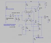
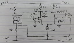
Attached is the circuit diagram of "my" solution. BTW the clone maker uses newer Japanese transistors than the original J212 and J175 JFETs and the then ubiquitous 2N4401 and 2N4402.
Transistors are 2SJ103BL and 2SK246BL for the JFETs and 2SC2705 & 2SA1145 for the bipolars. Passive components are also changed (obviously).
Anyway.
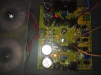
I simply built the circuit, adjusted the power rails to +/- 15V and adjusted offset (all by trimpotentiometers). Then added RCA in and out jacks, connected an iPhone to the input and the output went to my Pass DIY B-1. The circuit played music.
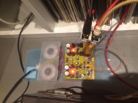
Then power off, and I added some old Plessey 4.7 polypropylene DC blocks at the input, see the picture. Bias should have come via 2k7 resistors from +15V, but I only had 4k22 as the closest higher value. So those were soldered in, and I simply connected everything together and played a record, and it sounded nice enough.
The gain of the circuit is intended quite a lot higher. Simulations indicates this should work. For now the gain is set by 10k and 3k3 to 4x or 12dB.
A word about the 4k22 (or 2k7) bias resistors. Both goes to +15V as there was two nice and handy plated holes for this. But I believe one of them could go to the -15V rail to preserve the phase. I did not care to swap the headshell leads at this time.
Things to do and test out:
What I do not intend to do is find a better sounding capacitor than the Plesseys.
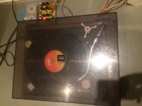
The test were performed with my old JVC Nivico SRP-473E and with a Technics National Panasonic Matsushita EPC-460 strain gauge cartridge. It all played, as mentioned, into the B-1 preamplifier/buffer. Power amplifier was a Parasound 2125 as my Pass PCBs still are laying around populated between 0 and 100%.
It sounded nice enough I believe, but the volume control was well above 11. (11 o'clock that is.)
I have not done anything with regard to shelf filters. The late Lou Dorren once said the EPC cartridges was (to some degree) corrected (mechanically). I have done some simulation, and I will look at the possibility to add a switch and a small Veroboard with a shelf filter that can be switched in and out.
Rolv-Karsten
PS. Pictures to come.
BTW Here is another SG cartridge amplifier.
Some time ago I started a thread with the intention to make a strain gauge cartridge amplifier based on Nelson Pass' "LSK" pre-amplifier. But I decided to change approach. Searching ebay for other PCBs I came across one of the clones of the old John Curl JC-2 circuit from the seventies. The Chinese guys does not provide the best of DIY descriptions, but I knew the circuit from a long time ago as I built my forst clone in 1981 based on the old "Audio Amateur" circuits published by John Curl himself.
Buying this PCB complete with components, but without a transformer, costs just below USD30.
Attached is the circuit diagram of "my" solution. BTW the clone maker uses newer Japanese transistors than the original J212 and J175 JFETs and the then ubiquitous 2N4401 and 2N4402.
Transistors are 2SJ103BL and 2SK246BL for the JFETs and 2SC2705 & 2SA1145 for the bipolars. Passive components are also changed (obviously).
Anyway.
I simply built the circuit, adjusted the power rails to +/- 15V and adjusted offset (all by trimpotentiometers). Then added RCA in and out jacks, connected an iPhone to the input and the output went to my Pass DIY B-1. The circuit played music.
Then power off, and I added some old Plessey 4.7 polypropylene DC blocks at the input, see the picture. Bias should have come via 2k7 resistors from +15V, but I only had 4k22 as the closest higher value. So those were soldered in, and I simply connected everything together and played a record, and it sounded nice enough.
The gain of the circuit is intended quite a lot higher. Simulations indicates this should work. For now the gain is set by 10k and 3k3 to 4x or 12dB.
A word about the 4k22 (or 2k7) bias resistors. Both goes to +15V as there was two nice and handy plated holes for this. But I believe one of them could go to the -15V rail to preserve the phase. I did not care to swap the headshell leads at this time.
Things to do and test out:
- Test with one channel biased from -15V
- Increase the gain by changeing the 10k feedback resistor to e.g. 100k
- Check stability - e.g. parallell the feedback resistor with 10pF or something
- Put the circuit board and the transformer in an enclosure
- Add a power switch and a fuse (I just plugged it into the wall not caring about fuses or anything. Don't do that!
What I do not intend to do is find a better sounding capacitor than the Plesseys.
The test were performed with my old JVC Nivico SRP-473E and with a Technics National Panasonic Matsushita EPC-460 strain gauge cartridge. It all played, as mentioned, into the B-1 preamplifier/buffer. Power amplifier was a Parasound 2125 as my Pass PCBs still are laying around populated between 0 and 100%.
It sounded nice enough I believe, but the volume control was well above 11. (11 o'clock that is.)
I have not done anything with regard to shelf filters. The late Lou Dorren once said the EPC cartridges was (to some degree) corrected (mechanically). I have done some simulation, and I will look at the possibility to add a switch and a small Veroboard with a shelf filter that can be switched in and out.
Rolv-Karsten
PS. Pictures to come.
BTW Here is another SG cartridge amplifier.
Attachments
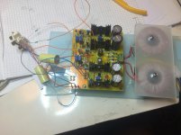
Pictures of JC-2 based strain gauge cartridge amplifier
Please find attached some pictures of my "demonstrator" circuit.
Of course, I will be more than happy to read your proposals for improvements, and even downright stupid things I have done.
One thing I also plan to test is to try my Stax CP-Y/II cartridge as a source. I believe this should work as well. Comments anyone?
/RK
PS. Please also start a discussion on shelf filters (or other solutions for the RIAA deviations).
Attachments
Last edited:
(from post 1)Opposite polarities on bias to avoid an inverting stage, or swapping cartridge leads.
Any comments?
/RK
But I believe one of them could go to the -15V rail to preserve the phase. I did not care to swap the headshell leads at this time.
Please note that swapping the leads of the pickup does not invert the phase, because the element is resistive, it is no "generator".
To change the polarity (invert the phase) of one channel, the bias current has to be reversed, as to your idea to use the -15 volts supply on one channel.
Yes, correct. The Epc-450 etc and the Stax, Sao Win SG etc are not generators. Capacitor transducers are to known to have great merit elsewhere, microphones, electrostatic speakers, so why not here? (The EPC-450 etc are not capacitors as known, but still...)
One "problem" is of course the RIAA curve. I believe shelf filters (or a DSP) is more than a good idea. But not tonight
One "problem" is of course the RIAA curve. I believe shelf filters (or a DSP) is more than a good idea. But not tonight
I have a WIN strain gauge and was reading this thread with interest until I saw this link. That was 4 years ago!! I still use that circuit and it works well but I have redesigned the input. My audio buddy is using the updated circuit and reports that he didn't notice any significant change when updating the circuit so I haven't rushed in yet and made the changes myself. In short, the changes are:Some time ago I started a thread with the intention to make a strain gauge cartridge amplifier based on Nelson Pass' "LSK" pre-amplifier. But I decided to change approach. Searching ebay for other PCBs I came across one of the clones of the old John Curl JC-2 circuit from the seventies. The Chinese guys does not provide the best of DIY descriptions, but I knew the circuit from a long time ago as I built my forst clone in 1981 based on the old "Audio Amateur" circuits published by John Curl himself.
Buying this PCB complete with components, but without a transformer, costs just below USD30.
Attached is the circuit diagram of "my" solution. BTW the clone maker uses newer Japanese transistors than the original J212 and J175 JFETs and the then ubiquitous 2N4401 and 2N4402.
Transistors are 2SJ103BL and 2SK246BL for the JFETs and 2SC2705 & 2SA1145 for the bipolars. Passive components are also changed (obviously).
Anyway.
I simply built the circuit, adjusted the power rails to +/- 15V and adjusted offset (all by trimpotentiometers). Then added RCA in and out jacks, connected an iPhone to the input and the output went to my Pass DIY B-1. The circuit played music.
Then power off, and I added some old Plessey 4.7 polypropylene DC blocks at the input, see the picture. Bias should have come via 2k7 resistors from +15V, but I only had 4k22 as the closest higher value. So those were soldered in, and I simply connected everything together and played a record, and it sounded nice enough.
The gain of the circuit is intended quite a lot higher. Simulations indicates this should work. For now the gain is set by 10k and 3k3 to 4x or 12dB.
A word about the 4k22 (or 2k7) bias resistors. Both goes to +15V as there was two nice and handy plated holes for this. But I believe one of them could go to the -15V rail to preserve the phase. I did not care to swap the headshell leads at this time.
Things to do and test out:
- Test with one channel biased from -15V
- Increase the gain by changeing the 10k feedback resistor to e.g. 100k
- Check stability - e.g. parallell the feedback resistor with 10pF or something
- Put the circuit board and the transformer in an enclosure
- Add a power switch and a fuse (I just plugged it into the wall not caring about fuses or anything. Don't do that!
What I do not intend to do is find a better sounding capacitor than the Plesseys.
The test were performed with my old JVC Nivico SRP-473E and with a Technics National Panasonic Matsushita EPC-460 strain gauge cartridge. It all played, as mentioned, into the B-1 preamplifier/buffer. Power amplifier was a Parasound 2125 as my Pass PCBs still are laying around populated between 0 and 100%.
It sounded nice enough I believe, but the volume control was well above 11. (11 o'clock that is.)
I have not done anything with regard to shelf filters. The late Lou Dorren once said the EPC cartridges was (to some degree) corrected (mechanically). I have done some simulation, and I will look at the possibility to add a switch and a small Veroboard with a shelf filter that can be switched in and out.
Rolv-Karsten
PS. Pictures to come.
BTW Here is another SG cartridge amplifier.
1. Old circuit is single end in, differential out. New circuit is diff in, diff out. This matters to me, because my power amps are differential and I like the idea of differential all the way.
2. The cartridge was direct coupled in original circuit, it is now capacitor coupled. In general I avoid in-line capacitors, but in this case it is actually a positive - the cap, in combination with the gate resistor, forms a high pass filter, that in combination with the natural roll-off of the SG, creates the response shelf below 50Hz, so the SG response is now a little bit closer to RIAA curve.
The circuit shown is a simple LTP as implemented by my mate, but it can easily be cascoded like my original circuit. The output sits at 12V dc so needs to be coupled via capacitor or transformer (I use a 1:1 Lundahl 1527XL).
One of the nice things about differential circuits is that attenuation is really easy. I have a 24 position switch wired across the drains of the LTP, first position is open circuit (no attenuation) and then other positions are taken up by other resistors which lower the load, and hence the gain of the LTP. This circuit feeds directly into my power amps. No pre-amp required! Also it is easy to reverse the phase on one channel by reversing the outputs of the LTP.
And the other advantage of differential circuit is that you don't need complementary devices. I think that complementary circuits are unnecessarily complicated. I'm a simple guy and I like simple circuits.
Attachments
R-K, pls see important update to my strain gauge circuit (now built and tested).Very elegant indeed. My solution is obviously too complicated compared. I like your differential approach. I just use the single ended B1 as a preamplifier.
http://www.diyaudio.com/forums/analogue-source/211081-strain-gauge-jfet-pre-amp-2.html#post4682324
Hi Hazard500
I just read it with great interest. Nice and simple.
I have not had any time for the SG amp the last few weeks.
I intent to lower the input cap and raise the gain and also increase the SG current to 5mA. I had it at around 3mA.
Later I might try to eq it by a passive shelf filter at the output (but buffered with a e.g a JFET follower.
Later ....
Hi Hazard500
I just read it with great interest. Nice and simple.
I have not had any time for the SG amp the last few weeks.
I intent to lower the input cap and raise the gain and also increase the SG current to 5mA. I had it at around 3mA.
Later I might try to eq it by a passive shelf filter at the output (but buffered with a e.g a JFET follower.
Later ....
I did a few changes simultaneously. I increased the current through the SG to 5mA, I reduced the input capacitor to 30nF and I increased the gain of the circuit to around 40dB by increasing the feedback resistor.
I also increased the noise (or it is much more audible now). I should have expected this...

So, I decided the solution shown above, plus the LSK probably, is to noisy. I found another solution with 2SK389V and 2SK109V in the front stage. Not exactly a "Papa" design, so it should probably not reside here. It is promising (just a quick test with PCB all over the floor). I shall finish it, take some pictures, and write up some lines about it just to conclude the thread. no more.
(from post 1)
Please note that swapping the leads of the pickup does not invert the phase, because the element is resistive, it is no "generator".
To change the polarity (invert the phase) of one channel, the bias current has to be reversed, as to your idea to use the -15 volts supply on one channel.
Right. I tried this, and biasing the right channel from +15V and the left from -15V gave me the same phase out from both channels. I used SB4X-002 "CD-4 Quadradisc 4-Channel/2-Channel Test Record" Test 4 (Band 5) and the Winscope SW on my PC to verify this.
/RK
Last edited:
- Status
- This old topic is closed. If you want to reopen this topic, contact a moderator using the "Report Post" button.
- Home
- Amplifiers
- Pass Labs
- BAF 2013 folded cascode LSK Pre line amplifier adapted for strain gauge cartridge