Another recommend for "alweit" Iv'e had both jfets/MOSfet from the DIY store and alweit over the years and I can't hear/tell any sonic differences between either. My issue (as many in UK/Europe) are the duties and shipping, making the DIYstore items + 50% purchase price and a wait of 4 weeks + for delivery from the USA. Alweit (being based in Israel) shipping is much less and only 7 days for delivery, usually.
That’s the reason why I’m thinking about purchasing from Alweit.
I am very thankful that the diyaudio store sells the complete packages, and have ordered all of my F6 parts there. But waiting for 4+ weeks on shipping means playing my music in mono for 4 weeks, so I will order a matched quad at Alweit.
Thanks for your feedback on this, I fully agree.
Koos
I copy from the speech of Mr. Pass about the F6-amp (Burning Amp Festival 2012):
In this circuit, the input Jfets were chosen for Idss at 8 mA or so, but you can get them with Idss up to 20 mA, which times the 23 volt supply will exceed their 0.4 watt rating. Or you might try some other Jfets with higher Idss or higher supply voltages. If you find that you need to degenerate the input Jfets with some resistance, you will find that there is little or noperformance penalty for small resistance values.
You can read the complete text on the FirstWatt-site. Articles - 2012 - F6 Talk at Burning
Amp festival 2012
Greets
Dirk
Interesting to know, I can get them up to 20mA.
I will order a matched quad close to 8mA, just for the peace of mind.
")
Thanks for the help!
Koos

I have been in contact with Alweit (Alex), and he has some limited stock of BL grade. He will send me a matched quad of 2SK170BL/2SJ74BL in the 7 - 8 mA range.
Thanks for all the advise that you guys gave me Without your help I would have been searching for days to find what I found today.
Koos
Thanks for all the advise that you guys gave me
Without your help I would have been searching for days to find what I found today. Koos
I have been in contact with Alweit (Alex), and he has some limited stock of BL grade. He will send me a matched quad of 2SK170BL/2SJ74BL in the 7 - 8 mA range.
Thanks for all the advise that you guys gave me
Koos
Happy to read that Alweit's able to supply the jfets. Now comes the
hard part of desoldering the old jfets and waiting for the new ones to arrive.
Desoldering of the old JFET’s on the channel which is out of service now was no problem, so I am confident that the other channel will be fine too. I keep a little tension on the leg of the JFET that I want to desolder with a small plier and this works out nice. The waiting is no problem as well, because it will only take 7 days of shipping from Israel to The Netherlands. That’s peanuts compared to the shipping from the diyaudio store to The Netherlands (4+ weeks).
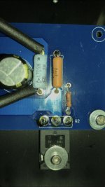
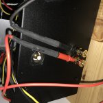
R4 on fire!
I have been listening to the F6 in mono mode for an hour or so (after one channel went down as described in previous posts) and really enjoying the clean sound that is was producing (Miles Davis - Kind of Blue is a one of a kind recording, and at 192khz out of the class a stage of the Gustard X20 pro direct into the F6 it was such a clean trumpet sound, did not want to stop listening).
After an hour of listening I started playing with the settings of the Gustard, and switched from 0dB gain to +12dB gain. Couple of minutes after that the music stopped, and smoke came out of the F6 (photos will follow as soon as I am able to upload them).
I quickly unplugged the power cord (I bypassed the fuse and powerswitch in the chassis, so the power cord is directly attached to the 230V leads of the transformer).
When looking closely I saw that resistor R4 was black, and when powering up for a short moment there was smoke coming off R4. The first thing that came to my mind was that this had something to do with my gain setting of the DAC/preamp. I thought that the increase of gain burned the resistor, so desoldered the burned resistor at R4 and replaced it by the R4 resistor from the other channel.
When I powered up the F6 after that, without anything attached to it (I disconnect the cables from preamp and unplugged the loudspeaker cables), there was again smoke coming from R4 after 20 seconds.
Does this issue sound familiar to someone?
(I have 2 short movies as well, but cannot upload them since they are .MOV files and there is only an option to upload MP4. If needed I can always try to convert the file).
Any help or advise is much appreciated!
Thanks in advance.
Koos
do you have a multimeter?
Sure, two pieces.
then you could use any of these two, while powering up , to check is there any DC offset on output ?
and there it must be , sole explanation for burned R4 (ref. sch in post #1)
check output mosfets , replace what's burned
best to remove them both and re-check do you have proper function of biasing voltage trimpots.... meaning - observing voltage at gate resistors confirming voltage values on both end trimpot positions
during mounting of mosfets - proper torque , big washer, split washer , continuity with heatsink check ...... all these are necessary details
BuB = Beware of Burrrrrrrrrrrrrrrrrs
then you could use any of these two, while powering up , to check is there any DC offset on output ?
and there it must be , sole explanation for burned R4 (ref. sch in post #1)
check output mosfets , replace what's burned
best to remove them both and re-check do you have proper function of biasing voltage trimpots.... meaning - observing voltage at gate resistors confirming voltage values on both end trimpot positions
during mounting of mosfets - proper torque , big washer, split washer , continuity with heatsink check ...... all these are necessary details
BuB = Beware of Burrrrrrrrrrrrrrrrrs
Thanks for the help Zen Mod!
Unfortunately, I am not able to start faultfinding right now, but tomorrow I will have a chance to have a look at your recommendations.
Thank You.
Koos
then you could use any of these two, while powering up , to check is there any DC offset on output ?
and there it must be , sole explanation for burned R4 (ref. sch in post #1)
check output mosfets , replace what's burned
best to remove them both and re-check do you have proper function of biasing voltage trimpots.... meaning - observing voltage at gate resistors confirming voltage values on both end trimpot positions
during mounting of mosfets - proper torque , big washer, split washer , continuity with heatsink check ...... all these are necessary details
BuB = Beware of Burrrrrrrrrrrrrrrrrs
Zen Mod,
You were right! (As I was expecting
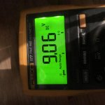
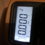
I measured the following:
• Across R2: 0,05V
• Across speaker terminals: 9,06V
I’m having issues with biasing. Mainly because I really don’t know what I am doing. I followed the bias instruction as explained in post #1 of this thread, but I am doing something in a wrong way I guess.
When turning P2 I see the voltage across R2 changing, but I cannot get it higher than 0,327V.
When I change the DC offset with P1 towards 0V the voltage across R2 is even getting lower than 0,327V.
I have no electrical background, so a Mickey Mouse kind of guidance of how to bias is welcome
Thanks in advance!
Koos
Attachments
- Home
- Amplifiers
- Pass Labs
- F6 Illustrated Build Guide