Q3 is fried, the 74.
Umm...isn’t Q3 a 170? I’ve never built the amp, just looking at the schematic on the first page of this thread.
Anybody selling a single matched pair?
I can probably help you out.
Its the 170, correct.
Although, i might be assuming that the jfet is busted..
I left it on for 5 minutes, and the result was that the 170 melted the strip holding the jfets together.
What would make it overheat? Jfet or resistors fault? If resistor, what resistor?
I actually have 2 pairs of matched toshiba 170s , maybe if i am really lucky it will match the 74. Would i need to desolder the 74 to check its ids?
Ok, I'll seek out some grade Bs.
Back to the hum(still have one working channel):
Should I hear ticks at the output when I touch the chassis with no input connected?
To me it sounds logical since ground is chassis bound. (Although elevated by CL60).
Should putting your hand between the jensen and input lead (mid air) produce groundloopy noises at output? Any measurements for poor connections to check?
Hum remains with shorted input, but is a bit lower.
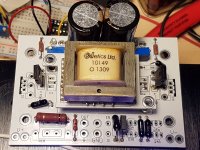
My newly built F6 has been running for a week with no issue so far.
However the supply rails are much higher than what is shown in the schematic.
I m having +/- 25.2v , but schematic printed +/- 23V.
My PS board is stock original from DiyStore, did i do something wrong ?
However the supply rails are much higher than what is shown in the schematic.
I m having +/- 25.2v , but schematic printed +/- 23V.
My PS board is stock original from DiyStore, did i do something wrong ?
If your power supply is actually making +/- 25v with the amplifier boards connected, that's wonderful!!
You don't need to change a thing and everything will run beautifully. (And you'll get a bit more output power as well.") )
)
22.5 seems to be most people's rails under load.
You don't need to change a thing and everything will run beautifully. (And you'll get a bit more output power as well.
)22.5 seems to be most people's rails under load.
Good to hear that, makes me less worry now.Thanks
Your supply voltage is probably higher than advertised by your utility.
I know mine is.I would not sweat the small stuff.
Ok, I'll seek out some grade Bs.
Back to the hum(still have one working channel):
Should I hear ticks at the output when I touch the chassis with no input connected?
To me it sounds logical since ground is chassis bound. (Although elevated by CL60).
Should putting your hand between the jensen and input lead (mid air) produce groundloopy noises at output? Any measurements for poor connections to check?
Hum remains with shorted input, but is a bit lower.
So, to continue my lone quest for unhumness, I have changed all but one input JFET. And now the hum is barely audible when i put my ear to the speaker (99db sensitivity). Hand movements do no longer induce noise. Perfect.
Not sure what happened, but now its time to enjoy some music.
Thank you very much for your advices; very useful for me.
As a conclusion: Certainly I'm also very interested in this UMS.
So, for the moment we are 4. Another one person and this good hope to become reality.
Did the USM 4U/400 chassis ever happen?
Dennis
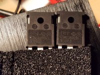
CREE C3M0280090
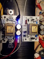
I recently picked up a set of Teabag convertible F6 boards from a fellow member and figured I should try breathing some life into them. Originally they were built to be used with Semisouth SiCs but I am planning to use those in F2J so this was going to be IRF.
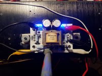
I put in 2 blue LEDS for ~6V and replaced the current limiting 10K resistor for 3K3 (if that's the right description for them) like a good Greedy Boy should. I put in the source degeneration 0.47R as well and jumped the 'extra' pot on the board. Without output devices the blue leds all light up and that's when I remembered I had Cree SiC that I bought last year and decided to use those instead of the IRF.
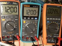
So bias pot and offset pots work very nicely and I measure from pots to ground and -V on each side and get both to read 1.2V steady. The problem is that the fets don't heat up and when I measure V across source resistors, there's nothing going through them. Do I need to bias these differently or change other part values to get the Cree SiCs to work here? Should I just use IRF instead and move on?
Voltage is +/- 24V and offset is about 4mV. I use bias pot to adjust one side and then offset pot to bring up the other side and adjust as needed.
The Cree SiC I am using is the C3M0280090:
C3M0280090 Datasheet
I recently picked up a set of Teabag convertible F6 boards from a fellow member and figured I should try breathing some life into them. Originally they were built to be used with Semisouth SiCs but I am planning to use those in F2J so this was going to be IRF.
I put in 2 blue LEDS for ~6V and replaced the current limiting 10K resistor for 3K3 (if that's the right description for them) like a good Greedy Boy should. I put in the source degeneration 0.47R as well and jumped the 'extra' pot on the board. Without output devices the blue leds all light up and that's when I remembered I had Cree SiC that I bought last year and decided to use those instead of the IRF.
So bias pot and offset pots work very nicely and I measure from pots to ground and -V on each side and get both to read 1.2V steady. The problem is that the fets don't heat up and when I measure V across source resistors, there's nothing going through them. Do I need to bias these differently or change other part values to get the Cree SiCs to work here? Should I just use IRF instead and move on?
Voltage is +/- 24V and offset is about 4mV. I use bias pot to adjust one side and then offset pot to bring up the other side and adjust as needed.
The Cree SiC I am using is the C3M0280090:
C3M0280090 Datasheet
Attachments
- Home
- Amplifiers
- Pass Labs
- F6 Illustrated Build Guide