....we can make further comments regarding trimpot characteristics.
that's what I am looking after
")
.
Some progress:
I got my current feedback F6 PCBs but when I was about to populate them I realized I accidentally inverted the pins of the transformer and misplaced the input JFET pins...
New boards have been ordered but in the mean time I have some working things to show off:
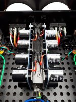
I have two UMS compatible virtual grounds that each convert 48V to +-24V. It is pretty much this circuit with a inrush thermistor, fuse and molex connectors. In the end both virtual grounds won't be on the same side but it was close by and convenient when I wanted to test them both =)
The other thing is my input transformer boards. My DAC has balanced output and as the F6 is eingle ended and my ground is now elevated at +24V I decided to use transformers to solve this. And while I'm at it I can parallel the primary so I get +6 dB input voltage. One thing that worked great is that the transformer boards have flip switches so I can switch between parallelling or series connecting the windings for -6, 0 and +6 dB voltage gain.
The heat sinking might be overkill, the case is a vertically mounted (10mm front is now the bottom) 350 mm deep SLIMLINE 3U where the amps are mounted individually on each side for easy tinkering. The heat sinking for each side is a 5U 400mm UMS heat sink for the bassmid amp (F6) and 120x400 heat sinks on the bottom for the tweetamp. A lot of heat sinking in a small package =)
I got my current feedback F6 PCBs but when I was about to populate them I realized I accidentally inverted the pins of the transformer and misplaced the input JFET pins...
New boards have been ordered but in the mean time I have some working things to show off:
I have two UMS compatible virtual grounds that each convert 48V to +-24V. It is pretty much this circuit with a inrush thermistor, fuse and molex connectors. In the end both virtual grounds won't be on the same side but it was close by and convenient when I wanted to test them both =)
The other thing is my input transformer boards. My DAC has balanced output and as the F6 is eingle ended and my ground is now elevated at +24V I decided to use transformers to solve this. And while I'm at it I can parallel the primary so I get +6 dB input voltage. One thing that worked great is that the transformer boards have flip switches so I can switch between parallelling or series connecting the windings for -6, 0 and +6 dB voltage gain.
The heat sinking might be overkill, the case is a vertically mounted (10mm front is now the bottom) 350 mm deep SLIMLINE 3U where the amps are mounted individually on each side for easy tinkering. The heat sinking for each side is a 5U 400mm UMS heat sink for the bassmid amp (F6) and 120x400 heat sinks on the bottom for the tweetamp. A lot of heat sinking in a small package =)
Attachments
New build woes
Hi folks,
I started my F6 build in the summer of '16 and off (mostly, what with work and health stuff) and on I’ve been sourcing the parts and populating the boards. Well, I put it together last year and then when the power supply didn’t work I put it to one side and sulked.
My previous experience was the ACA (worked first time) and I guess I got cocky trying this next. To cut a long and tedious story short, I have a working power supply, I think one working channel and a whole fist of questions...
Channel A seems to be working ( but the led doesn’t, in either polarity ) and biased but only to about 0.484V max . But the offset goes to 0V.
It had about 5 mins runtime; does it need longer to get up to temperature? And, I’m still doing this with the bulb limiter in place - which has a dim glow. Is this correct? Both doing it with the limiter in place and/or the dim glow.
Channel B plugged into either side of the power supply appears to have a short. The bulb limiter glows bright as soon as the power is applied so I haven’t attempted anything further. Where can I start to diagnose the issues?
Can anyone throw any light on my problems please?
Alistair
I should have added DIYaudio kit and parts as per the BOM on page 1.
Last edited:
Hi Alistair,
For channel B, check for soldering issues and anything like metal shaving puncturing
the insulator on the mosfets. Perhaps you can take some pictures of the board and
post them and folks might spot something.
I don't think you can bias the channel with the bulb limiter in place. So for channel A,
I suggest turning the bias back down (since you likely have turned it up quite high by
now) and start the bias procedure without the bulb limiter.
I suggest sorting out channel B first.
Cheers,
Dennis
Alistair,
As Dennis mentions, you can't bias with the bulb in place. If you remove the tester I suspect that channel will be fine.
However you do have an issue with the other channel if the bulb is staying bright.
Please post well-lit, in-focus photos, and we'll start to have a look.
As Dennis mentions, you can't bias with the bulb in place. If you remove the tester I suspect that channel will be fine.
However you do have an issue with the other channel if the bulb is staying bright.
Please post well-lit, in-focus photos, and we'll start to have a look.
Last edited:
Hi Alistair,
For channel B, check for soldering issues and anything like metal shaving puncturing
the insulator on the mosfets. Perhaps you can take some pictures of the board and
post them and folks might spot something.
I don't think you can bias the channel with the bulb limiter in place. So for channel A,
I suggest turning the bias back down (since you likely have turned it up quite high by
now) and start the bias procedure without the bulb limiter.
I suggest sorting out channel B first.
Cheers,
Dennis
Dennis, thanks. I’ll work on some pics and pop them up later.
I figured as much with the biasing. I’m jus put keen to have something before the festives, even it it was just mono...
Thanks again, Al
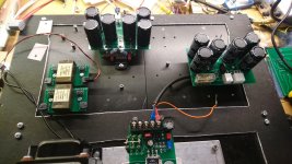
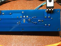
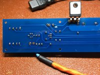
Diagnostic Pics
I’ve attached some pics. Let me know if they aren’t clear enough. I have more, I didn’t want to swamp the thread with pics.
6L6, thanks in particular to you. Without your guide(s) this would just be a dream.
Al
I’ve attached some pics. Let me know if they aren’t clear enough. I have more, I didn’t want to swamp the thread with pics.
6L6, thanks in particular to you. Without your guide(s) this would just be a dream.
Al
Attachments
Al,
Have you tried to turn down the bias on channel B with the tester in place? It's unlikely you'll hurt anything with it (bulb) connected.
Re-attach the board to the sinks and give it a go. If the bias pot does react properly (I.E., you can get the bulb to dim) than attempt to bias to about 1/4 of the suggested ammount and adjust DC offset to zero. Then remove bulb and measure
Al,
Have you tried to turn down the bias on channel B with the tester in place? It's unlikely you'll hurt anything with it (bulb) connected.
Re-attach the board to the sinks and give it a go. If the bias pot does react properly (I.E., you can get the bulb to dim) than attempt to bias to about 1/4 of the suggested ammount and adjust DC offset to zero. Then remove bulb and measure
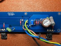
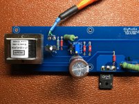
With tester in place, bias appears to read zero (Measuring across the legs of R2 - the green one just to the right of the cap in the first pic) and P2 does not seem to have any effect - no voltage or dimming of the limiter bulb.
There is a hot dust smell, but I can’t locate any hot spot/components.
Result!
Heated all the joints up again with a hot iron. Sorted. Must have had a duff joint despite them all looking right.
Both sides seem to be working. No LEDs functioning, but that might be down to buying the wrong thing. But both channels start up (individually and together) on the bulb tester with just a brief glow and then it goes off.
Right, now to swap leads and bias 🙂
I shall report back...
Thanks 6L6
Al
Hmmmmm. Ok, that's not right.
Look for poor solder joints, make sure your power connections are 100% proper, and doublecheck that you have no crumbs of metal in the Mosfet insulators.
Heated all the joints up again with a hot iron. Sorted. Must have had a duff joint despite them all looking right.
Both sides seem to be working. No LEDs functioning, but that might be down to buying the wrong thing. But both channels start up (individually and together) on the bulb tester with just a brief glow and then it goes off.
Right, now to swap leads and bias 🙂
I shall report back...
Thanks 6L6
Al
And bugger! I think I have fried A.
So B is biased 0.505V and almost 0V offset (it flickers around 0 buy +/- 0.4 mV). The LED works.
I moved to A, in my enthusiasm I forgot to wind back the bias (from my previous attempt to bias it with the limiter in place). It started at about 1.5v and as I was turning it off I noticed a wisp of smoke from the middle, coming up the back of the PCB from Q2 direction. Q2 was hot. As was R1. Both too hot to touch, but cooled quickly.
I have redone all the joints (swapped the LED round) and whilst there centred the bias and offset pots. I have re-tested with with the limiter in place (all good) and now I am getting nothing across R2, zero volts with the power on.
Have I cooked it? I hope not.
H
Any tips folks? I neee to get ordering the bits if I am to beat the Xmas post.
And bugger! I think I have fried A.
So B is biased 0.505V and almost 0V offset (it flickers around 0 buy +/- 0.4 mV). The LED works.
I moved to A, in my enthusiasm I forgot to wind back the bias (from my previous attempt to bias it with the limiter in place). It started at about 1.5v and as I was turning it off I noticed a wisp of smoke from the middle, coming up the back of the PCB from Q2 direction. Q2 was hot. As was R1. Both too hot to touch, but cooled quickly.
I have redone all the joints (swapped the LED round) and whilst there centred the bias and offset pots. I have re-tested with with the limiter in place (all good) and now I am getting nothing across R2, zero volts with the power on.
Have I cooked it? I hope not.
Any tips folks? I neee to get ordering the bits if I am to beat the Xmas post.
most likely just new mosfets
check source reistors , just in case
Thanks Zen.
Best get ordering.
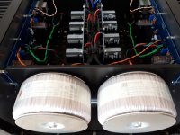
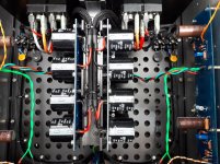
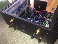
Another F6 Completed
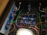
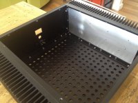
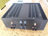
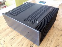
This is my first post (ever), and the F6 is my first DIY amplifier apart from a Bottlehead Crack some years ago. I would not have attempted this build without the clear instructions and pictures in this excellent guide. Manythanks to 6L6.
It all went exactly to plan. I used 5.6v Zeners and changed R7/8to 4.7K. Everything else is as per this guide. It must be said that having an assembly of unfamiliar parts come to life for the first time after tentatively adjusting some voltages, was a thrill not experienced since my youth (a verylong time ago), and happily, all without injury or release of magic smoke.
Some pictures are attached (Ihope) for proof of build. Chassis is mine, all aluminium, using Conradheatsinks. I went to a bit of effort to make it as integral as possible to increase thermal mass and surface area without increasing chassis size. Seems to work well with bias set at .59v
The build had a standard PSU at first because I was not game to deviate from basic instructions.
But I have since made it dual mono in preparation to try the F4 amp (yup, it’s true, you just can’t build oneof these things once you start). In fact I have just completed the BA3 pre-ampwhile waiting for the F4 parts to arrive (very bitten by this bug).
Thanks to Nelson Pass for sharing his art, to 6L6 for his work onthese guides and to ZM for his knowledge and humour along the way, and to allthose who contribute to this great DIY site.
Attachments
-
 Front above view.jpg860.4 KB · Views: 503
 -
 Above view.jpg352.5 KB · Views: 481
 -
 Original single PSU.jpg628 KB · Views: 775
 -
 Original layout.jpg476.2 KB · Views: 783
 -
 Chassis Internal.jpg633.1 KB · Views: 788
 -
 Chassis Rear.jpg889.8 KB · Views: 807
 -
 Chassis front.jpg311.5 KB · Views: 816
 -
 Dual Mono.jpg906.1 KB · Views: 501
- Home
- Amplifiers
- Pass Labs
- F6 Illustrated Build Guide