Yeah, that's roughly what I expected. The zener values are so low because there isn't enough current through
them for voltage regulation. You should be able to bring them closer to 5V with more current by changing R7/R8 to your 3k3 resistors. I suspect that may be enough to bias things up.
Of course, changing those resistors or the diodes will require dialing back on the pots before powering up; you don't want the current to jump up so much that you end up with a burning amp.")
them for voltage regulation. You should be able to bring them closer to 5V with more current by changing R7/R8 to your 3k3 resistors. I suspect that may be enough to bias things up.
Of course, changing those resistors or the diodes will require dialing back on the pots before powering up; you don't want the current to jump up so much that you end up with a burning amp.
Last edited:
Thanks Dennis,
I will make the change to the resistors in the next day or two and let you know the result. It is so great having this community and people like you to help out. I have been streaming from a Allo Signature Digione with a Chord Mojo acting as preamp and DAC through the F6 to a pair of vintage Tangent RS4 speakers and I keep getting mesmerized by the sound! ...even at this stage of the game.
Bruce
Dennis
PS - I'd welcome any tips on best ways to de-solder. I have a sucker and some of the copper weave tape and can get it done but it is a bit tedious and I have to lift the pcb so I can get at both sides in the process.
So I changed R7 and 8 yesterday on the right channel of the F6, while waiting on delivery of the leds to do the picodumb mod. That change enabled me to raise the bias on that side to 0.52v but perplexingly the offset is now 4.71 v (it was 0.06v before changing the resistors) and I cant get it any lower. Do you expect that installing the 3 LEDS to replace the 5.2v zeners will fix this problem? The voltage across the zeners on that same side remained the same at 4.6-4.8v.Yeah, that's roughly what I expected. The zener values are so low because there isn't enough current through
them for voltage regulation. You should be able to bring them closer to 5V with more current by changing R7/R8 to your 3k3 resistors. I suspect that may be enough to bias things up.
Of course, changing those resistors or the diodes will require dialing back on the pots before powering up; you don't want the current to jump up so much that you end up with a burning amp.
PS - I'd welcome any tips on best ways to de-solder. I have a sucker and some of the copper weave tape and can get it done but it is a bit tedious and I have to lift the pcb so I can get at both sides in the process.
Check the bias across R1 the .56 resistor to see what it is. You can also check the voltage on each side of the resistor you just installed. Check the resistors you installed to make sure they are the correct value, check for a cold solder joint and check continuity to the next point on the board touching the resistor lead.
When you are adjusting the DC offset, you are adjusting the bias of the 2nd mosfet to match the first one. So the problem is likely in the part of the circuit that ties to the 2nd mosfet closest to the transformer.
When desoldering, I use something like this to grab the leads:
https://www.testequity.com/product/...3oZPU2tKenbULQq7P3kO-OwicjQvsJYxoCaOwQAvD_BwE
Grab one side of the resistor, melt the solder on that side and pull the resistor end out. If the resistor is mounted too close to the board, you can melt the solder on one side and push the lead through the hole. This would give you enough room to grab the resistor. With that being said, I elevate all of my resistors off of the board a bit so that I can pull them, reuse, easily grab to test etc.
When you are ready to clear the hole, add more solder to the solder pad, melt it with the gun, move the gun out from in front of the hole while doing your best to still heat the solder, use the solder sucker. The holes on these boards have pads on both sides and throughout the inside of the hole which makes it a little tougher to suck all of the solder out which is why you need the heat. I keep my soldering gun at around 625F for removing solder. About 525F for desoldering.
Best of luck!
The low voltages across the zeners means they are still not regulating and they are not high enough to allow the mosfets to 'turn on' at the current required. The dc offset means that at the max adjustments of your trimpots, one mosfets is drawing more current than the other. (Parts variation of the mosfets and the different in the observed zener voltage contribute to this.)
Assuming 23V rails, 5K trimmers and 3.3K R7/R8, that should give over 4mA through the zeners and I would have hoped (expected) that they would be enough for them to regulate. Sorry that didn't work.
Can you please check that the trimmers are 5K and not something lower?
As long as you get the expected voltage with the LEDs installed, you should be able to set the bias and dc offset correctly.
Mike and Dennis,
The voltage across R1, the 0.56 ohm resistor, is 0.57. The voltage across the resistor I just installed R7, the 3.3k one, is 1 or -1, depending on the polarity of the leads. Not sure what that means. Other resistors in the area of the offset pot are:
R11 0v
R9 0v
R4 0.47v
R6 0v
Double checked the trimmer is indeed a Bourn 20 turn 5k trimmer as specked. I am inclined to agree with Mikes speculation that something is amiss in the circuit for the offset mosfet near the transformer. I have not checked for cold solder joints yet but I did take extra care to inspect and make sure every joint was well filled when putting the board together since I had a bad solder joint in one of my Amp Camp amps last year and did not want to repeat that mistake. I amhoping I don't have a failed component somewhere in the circuit. Looking forward to your thoughts.
Mike,
The green LEDs arrived today for the pico dumb mod and I just wanted to double check is this supposed to replace only the bias Zenor z2 or both zenors?
also I would appreciate your and Dennises feedback on whether it makes sense to push ahead on the picodumb mod or should I wait until we resolve what’s going on currently with my board that has the 10 K resistors replaced by the 3.3 K resistors.?
Try it and report back. If the reading on the 0.56ohm resistor is .570v , you should have around the difference between it and the other source resistor. Around 50mv offset. .570v-.520v.Mike,
The green LEDs arrived today for the pico dumb mod and I just wanted to double check is this supposed to replace only the bias Zenor z2 or both zenors?
also I would appreciate your and Dennises feedback on whether it makes sense to push ahead on the picodumb mod or should I wait until we resolve what’s going on currently with my board that has the 10 K resistors replaced by the 3.3 K resistors.?
Changing to the LEDs shouldn't hurt anything. If they don't light up, then they need to be turned around. There should be some pictures in the Pico mod thread towards the last page.
Yeah, go for it. And remember to dial back down the pots before powering up.
Some pics from Mike on post #92:
https://www.diyaudio.com/community/...y-dumbest-idea-yet.348969/page-5#post-6851970
Some pics from Mike on post #92:
https://www.diyaudio.com/community/...y-dumbest-idea-yet.348969/page-5#post-6851970
Uh-Oh...Before I proceed further there is a new development, while taking some further measurements this afternoon I moved the amp and it seems to have shorted and blew a fuse (only one of the two). I have been searching for the short. The amp did come to life (all leds came on) after changing the fuse and I started it on the dim bulb tester but it seemed to be drawing more current (bulb brighter) than before so I did not keep it on. I have been using a continuity checker to search for the short starting where the power comes into the amp while grounding the checker on the chassis. There appears to be no short in the power supply when disconnected from the cl-60 that connects to the star ground but when the cl-60 is connected there is a short. So my question is is the cl-60 supposed to conduct current or is it possible this one was destroyed by the short or, possibly, caused the short? And should the CL-60 be replaced? Not exactly sure what I am doing or looking for. Any help appreciated.
If the CL-60 is not the problem, then I suppose I would disconnect the amp PCBs from the power supplly and turn the power supply on and see what happens. Then connect the pcbs one at a time and see what happens. Good idea or bad?
If the CL-60 is not the problem, then I suppose I would disconnect the amp PCBs from the power supplly and turn the power supply on and see what happens. Then connect the pcbs one at a time and see what happens. Good idea or bad?
Last edited:
The CL-60's purpose is to reduce the inrush current when you turn the amp on. It is supposed to have some resistance when the amp turns on, then the resistance reduces as more power flows through it.
Remove the amplifier board that has been in question from the power supply circuit and turn the amp back on. That should narrow the problem to either the other channel or the power supply.
Remove the amplifier board that has been in question from the power supply circuit and turn the amp back on. That should narrow the problem to either the other channel or the power supply.
Bruce,
Are you talking about TH1 on the 3rd pic (PS schematics) on the first post?
https://www.diyaudio.com/community/threads/f6-illustrated-build-guide.277850/
Normally there shouldn't be current flowing through it. Its resistance at room temp should be around 10-ish ohms, so depending on your meter, it might be low enough to trigger continuity. You might want to disconnect it at one end and just measure its resistance and see if it's as expected. If it checks out, it's likely ok. You can continue as you had planned.
Hi everyone, newbie diy builder here on my first project ever for this F6
I have stuffed all PCBs and am in the process of wiring the power supply. I realized the transformer I bought only has one set of primary wires (see picture attached: black and white wires). This prevents me from setting up the thermistor as indicated in the schematics. What does that mean in practical terms and is there a way to make it work? Should I just get another transformer with dual set of primary wires?
Thanks a lot for all your past and future comments which are a giant help for beginners like me.
Arthur
Attachments
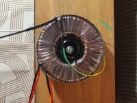
That looks like a decent transformer. It Ok to just use a single thermistor in the primary wires (either hot or neutral). I prefer the CL-70 for inlet current reduction. They will get warm in operation.
Make sure you tie the green/yellow safety ground wire to the chassis separately next to where the AC inlet is.
Make sure you tie the green/yellow safety ground wire to the chassis separately next to where the AC inlet is.
Thanks a lot for the quick feedback! So just to rephrase I should put a thermistor in series with either hot or neutral wires, and because it's not in a dual primary wires config you advise a CL70.That looks like a decent transformer. It Ok to just use a single thermistor in the primary wires (either hot or neutral). I prefer the CL-70 for inlet current reduction. They will get warm in operation.
Duly noted, I'll tie it on the chassis, separate from the other ground wires.Make sure you tie the green/yellow safety ground wire to the chassis separately next to where the AC inlet is.

Yes we are talking about TH1 and it measures 14 ohms. I disconnected the channel of the amp that I have been working on and the power supply and left channel looked normal when I powered up.Bruce,
Are you talking about TH1 on the 3rd pic (PS schematics) on the first post?
https://www.diyaudio.com/community/threads/f6-illustrated-build-guide.277850/
Normally there shouldn't be current flowing through it. Its resistance at room temp should be around 10-ish ohms, so depending on your meter, it might be low enough to trigger continuity. You might want to disconnect it at one end and just measure its resistance and see if it's as expected. If it checks out, it's likely ok. You can continue as you had planned.
Is it possible that not having the PCB and IRFPs firmly bolted to the heat sink could cause a short? Because that’s the way I had it when I was testing.
- Home
- Amplifiers
- Pass Labs
- F6 Illustrated Build Guide