Maybe, but probably just forgotten - I missed it too
The basic GB bridges are very convenient and having all four diodes on the one substrate makes for closely matched performance so it'd be pretty unusual to get one to be faulty but maybe one leaky diode might create something like the problems here - it's certainly a puzzle.
The basic GB bridges are very convenient and having all four diodes on the one substrate makes for closely matched performance so it'd be pretty unusual to get one to be faulty but maybe one leaky diode might create something like the problems here - it's certainly a puzzle.
At the moment I think the most likely problem is:
1) DC on the mains
2) Faulty Bridge rectifier
3) Or something dumb that has been overlooked, eg incorrect installation of ground lift
thermistor or poor quality connections etc.
4) Maybe hum is being picked up on the Jensen from other electrical equipment nearby.
With 90dB speakers, there should be dead silence at his speakers.
It's not terrible but there is something not right, it would be in his interest persisting with it to get it fixed.
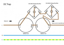
Here is one example of a dc blocker circuit. I think some member posted it but it's essentially the same as the Rod Elliot one but with greater DC blocking potential
Not hard to build at all. I would use caps with screw terminals.
Just add more bridges in series if the level of DC is quite high.
2 bridges should be sufficient though.
Not hard to build at all. I would use caps with screw terminals.
Just add more bridges in series if the level of DC is quite high.
2 bridges should be sufficient though.
Attachments
Last edited:
Yep, totally agree about using the "better" caps in the dc trap - it does make a difference - and remember 'peranders' dc traps that use different number of diodes to counter higher levels of the dc component - still available, I think.
Unfortunately, we're having to add line filters too to reduce online 'rubbish' and in some places, the ground return can be highly compromised and require floating/balanced systems or expensive regeneration - I know a guy who lives in Melb city centre has this problem - it's extremely frustrating and changes during the day/night too!
The switchmode power systems are progressing quickly and we'll all soon be using these along with the increasing domestic Solar regeneration - maybe we'll get a giant Tesla battery like SA that seems to be functioning so well ...
I noticed when testing CRC power supplies that applying a 5kHz low pass filter on the scope eliminated what appeared to be 90% (or more) of the high frequency noise on the ripple.
I would like to know how low we are permitted to filter on the AC mains. If we are permitted to filter down to 5kHz I would be happy with that, if lower even better.
I would like to know how low we are permitted to filter on the AC mains. If we are permitted to filter down to 5kHz I would be happy with that, if lower even better.
Last edited:
With the test wires shorted?
Sorry, I missed the context of your question. Which post are you referring to?
With the test wires shorted?
About the only thing you haven't tried replacing block bridges, unlikely as it may seem - you might be unlucky to get a faulty one - hope your meter turns out okay, they're usually a pretty reliable product.
Well, I do have one spare of a different brand I could try. Or I could just order new ones. They’re cheap enough...
He might have half bridge rectification if one of the diodes is dead.
I did suggest replacing them earlier but I guess it probably got a bit too much for him.
I Guess I did miss that post. Or perhaps I tested them
 . Too much? No! I’m the Cool Hand Luke of troubleshooting. (That’s a Paul Newman movie reference for anyone unfamiliar).
He might have half bridge rectification if one of the diodes is dead.
I did suggest replacing them earlier but I guess it probably got a bit too much for him.
At the moment I think the most likely problem is:
1) DC on the mains
2) Faulty Bridge rectifier
3) Or something dumb that has been overlooked, eg incorrect installation of ground lift
thermistor or poor quality connections etc.
4) Maybe hum is being picked up on the Jensen from other electrical equipment nearby.
With 90dB speakers, there should be dead silence at his speakers.
It's not terrible but there is something not right, it would be in his interest persisting with it to get it fixed.
My thought is that I do have noise/DC on the mains. However, replacing the Bridge Recifers is inexpensive and easy, so I will do that as well.
If the issue is with something in your items 3 or 4, shouldn’t I be able to change the amplitude of the hum in some way?
Here is one example of a dc blocker circuit. I think some member posted it but it's essentially the same as the Rod Elliot one but with greater DC blocking potential
Not hard to build at all. I would use caps with screw terminals.
Just add more bridges in series if the level of DC is quite high.
2 bridges should be sufficient though.
This is nice and simple - ordering parts to play around with it. Thanks!
My thought is that I do have noise/DC on the mains. However, replacing the Bridge Recifers is inexpensive and easy, so I will do that as well.
If the issue is with something in your items 3 or 4, shouldn’t I be able to change the amplitude of the hum in some way?
Good plan.
In your case I think the best approach is probably going to be to eliminate every potential possibility until you find the cause.
This could be tedious but on the other hand by the time you have this fixed, your amp will be as good as it possibly can be, likely even better than if you never had the problem in the first place.
I think the possibility of a bad capacitor should be left as the last resort.
I generally measure every component before it goes in, that includes capacitors, just so I don't have to think about these kinds of problems. I hate desoldering, not that it's hard, but you're risking causing damage to the pcb or components that might actually be good.
Having an oscilloscope is worthwhile, maybe a birthday present to yourself.
Last edited:
This is nice and simple - ordering parts to play around with it. Thanks!
If you're just going to use it for the amp alone get caps with a ripple rating above 5A.
If you decided you wanted to mount this in a box then connect up a power board to run everything from then we will need to change the cap sizes and ripple ratings etc.
Your voltmeter display was fluctuating.Remove testleads from meter, or short them together to see if the display gets stable.Sorry, I missed the context of your question. Which post are you referring to?
Here is one example of a dc blocker circuit. I think some member posted it but it's essentially the same as the Rod Elliot one but with greater DC blocking potential
Not hard to build at all. I would use caps with screw terminals.
Just add more bridges in series if the level of DC is quite high.
2 bridges should be sufficient though.
Good plan.
In your case I think the best approach is probably going to be to eliminate every potential possibility until you find the cause.
This could be tedious but on the other hand by the time you have this fixed, your amp will be as good as it possibly can be, likely even better than if you never had the problem in the first place.
I think the possibility of a bad capacitor should be left as the last resort.
I generally measure every component before it goes in, that includes capacitors, just so I don't have to think about these kinds of problems. I hate desoldering, not that it's hard, but you're risking causing damage to the pcb or components that might actually be good.
Having an oscilloscope is worthwhile, maybe a birthday present to yourself.
The Fluke 115 measures resistance and capacitance so I was able to measure everything before it went in the first time.
I like your idea of an Oscilloscope. I have been looking at two hobbyist scopes. The Rigol DS1202Z-E and the Siglent SDS1202X-E. These look like they might be the same scopes with different branding, so I’ll probably just roll the dice on one. Any advice?
If you're just going to use it for the amp alone get caps with a ripple rating above 5A.
If you decided you wanted to mount this in a box then connect up a power board to run everything from then we will need to change the cap sizes and ripple ratings etc.
I’ll start with the amp and will scale this thing later if needed. Thanks!
Het Glen,
If you're going to get a couple more 'block bridges' then don't get cheap ones but the quieter Schottky versions, if you can find them - maybe IXYS, Cree, etc
I am not finding Schottky bridges close to the size I think I need here (40v 30a?). Do these really help in this application? I read that Schottky diodes are better in mid-high frequency situations such as in switch mode power supplies. Thanks!
Your voltmeter display was fluctuating.Remove testleads from meter, or short them together to see if the display gets stable.
Ah, okay - nope, it still jumps. I replaced the dead fuse but that didn’t do anything for the nervous display.
- Home
- Amplifiers
- Pass Labs
- F6 Illustrated Build Guide