You bought the F6 'kit' from the diyaudio store? It comes with the PCB...
Sorry.. I wasn't very Clear.
PS pcb was foolishly Not purchased, at the same time as the F6 pcb/jensens/ transistors.
PS; Glad to read that yer Tannoys please with the new amp
Tannoys REALLY respond to gear upgrades, been amazing me in that regard for 40+ years.
Last edited:
It should not be hard to cobble together a PSU for this amp. Plenty of examples with and without PCBs. There are other PSU PCB sellers that sell boards, perhaps with less shipping cost to your location.
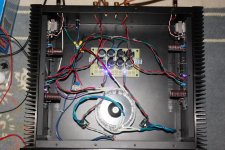
I decided to try a PSU without a PCB this go round. I got some capacitors with screws, and plan to stand them up after the bridge rectifiers. Gets harder if you want to put a snubber in. Adding a bleeder resistor and LED+resistor is a must IMO.
I decided to try a PSU without a PCB this go round. I got some capacitors with screws, and plan to stand them up after the bridge rectifiers. Gets harder if you want to put a snubber in. Adding a bleeder resistor and LED+resistor is a must IMO.
Great ! Thanks.. the PS isn't ...that.. complex an item, when all is said and done ")
I'll use the Schematic and fit it onto cheapish perf board.
Just didn't really want to spend 70$ ! (cdn) for a single premade pcb... unless there was clear and obvious advantage.
I'd rather buy recordings, if possible
I'll use the Schematic and fit it onto cheapish perf board.
Just didn't really want to spend 70$ ! (cdn) for a single premade pcb... unless there was clear and obvious advantage.
I'd rather buy recordings, if possible
Ermmm. Been soldering in my just received from Mouser bits onto the DIY F6 pcbs.
Became confused about polarity of the 'blue' Leds... Still Am, as there's No indication that I can deduce.
(can I run leads out from the PCB and panel mount the Leds? once someone tells me which end is + on the led holes and if it's the longer leg on the led)
Sooo..I started to read the entire thread in detail.. looking for 'blu' LED polarity Clues.
So I trip over the 9.1v zeners controversy... sighhh.
Yess I forgot your note Dennis
Am fitting irfp240's by the way.
So What then?? Is the final, agreed upon... proven correct... zenner V /resistor combination/ configuration ??
Just a Newbie here.
Just curious: IF the 9.1v IS wrong.... why is it still in the BOM?
Removing soldered in bits always seems to mess the thru plated holes (in the least)
Thanks
Last edited:
Sooo..I started to read the entire thread in detail.. looking for 'blu' LED polarity Clues.
Put them in last. They will only light up if in properly.
I'm not being factious.
Enough zener voltage to get the amp biased at temperature. Probably a volt or a bit more than the 5.1, but it's super dependent on the Vgs of your particular Mosfet, so it's a moving target. The pot helps take up some slack...So I trip over the 9.1v zeners controversy... sighhh.
So What then?? Is the final, agreed upon... proven correct... zenner V /resistor combination/ configuration ??
Just a Newbie here.
Zen mod said make zener 6.8V and replace the 10K resistor with 3.3K, that is as good advice as any to start.
I'll fix that.Just curious: IF the 9.1v IS wrong.... why is it still in the BOM?
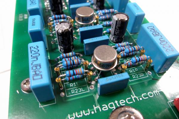
Desoldering is difficult, yes. Put some pins with female openings in that position and swap zener until you find your right value, like this -Removing soldered in bits always seems to mess the thru plated holes (in the least)
Last edited:
Thanks Looked at the traces.. seems the one from the Led Resistor being + ?
OK.. off to the local junk Purveyor in the AM for 3.3ks and a 6.8 v Z. Hope they have some. Replace Both R7 and R8 with 3.3ks ??
Dennis Hui said he got stable results with 9.1 V and r7, 8 as 3.3ks with his irfp240's.. Info read as good.. is it?
Ermm I needs adjust the blue Bournes to zero ohms to irfp source pin ?
Screw Clockwise or CCW till the adjuster bottoms (gently) ? Viewed from above with irfp's at the top ?
Not seen those wee tube things. I'll try find some
Snipping the leads and resistor off then applying a bamboo toothpick to the hole obstruction while heating it.. sometimes pops out the remaining wire bit harmlessly.
Although the wire snipping bit destroys the part being displaced. Small price when it works according to plan
Looked at the traces.. seems the one from the Led Resistor being + ? OK.. off to the local junk Purveyor in the AM for 3.3ks and a 6.8 v Z. Hope they have some. Replace Both R7 and R8 with 3.3ks ??
Dennis Hui said he got stable results with 9.1 V and r7, 8 as 3.3ks with his irfp240's.. Info read as good.. is it?
Ermm I needs adjust the blue Bournes to zero ohms to irfp source pin ?
Screw Clockwise or CCW till the adjuster bottoms (gently) ? Viewed from above with irfp's at the top ?
Not seen those wee tube things. I'll try find some
Snipping the leads and resistor off then applying a bamboo toothpick to the hole obstruction while heating it.. sometimes pops out the remaining wire bit harmlessly.
Although the wire snipping bit destroys the part being displaced. Small price when it works according to plan
Last edited:
Bare,
For the led, I suggest you check both boards since I seem to remember
on one board it was connected to the positive rail and on the other,
to the negative rail.
Both R7 and R8 should be changed. I used 9.1V/3.3k because I didn't
feel like ordering additional parts. Since you're buying additional parts,
I would just use Zen Mod and Jim's recommended values.
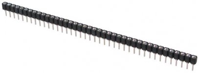
I haven't seen the sockets Jim used, but you should be able to find machine
pin sockets like the ones in the attached picture.
For the trim pots, I recommend (before soldering) you put a meter
on the part you plan to use and measure how the resistance changes
when you turn the pot. (And write this info down. )
Cheers,
Dennis
For the led, I suggest you check both boards since I seem to remember
on one board it was connected to the positive rail and on the other,
to the negative rail.
Both R7 and R8 should be changed. I used 9.1V/3.3k because I didn't
feel like ordering additional parts. Since you're buying additional parts,
I would just use Zen Mod and Jim's recommended values.
I haven't seen the sockets Jim used, but you should be able to find machine
pin sockets like the ones in the attached picture.
For the trim pots, I recommend (before soldering) you put a meter
on the part you plan to use and measure how the resistance changes
when you turn the pot. (And write this info down.
) Cheers,
Dennis
Attachments
bare-
I also marked with sharpie the direction to turn the pots to increase bias and offset as 6L6 did on one of his builds.
That's a great idea!
Great! thank You all
The hand holding is genuinely appreciated.
Off to the shoppe now.
Dubious as to what is actually available.
I may be having to leave in the 9.1's and using the 3.3k's.
With thoughts of minimising risk to the traces its a passable consolation, if 6.8v's are NA
Bournes are nicely soldered in ..well Dohhh.
Will meter them in place, I'll figure it out.
There is a directional pot adjust ? arrow silkscreened on my PCBs.
Sooo turning in arrow direction Increases Bias? Then opposite would Zero the pot?
Last edited:
Good and bad news:
I bought 4.... 6.8v Zeners, surprisingly these were available.
Unfortunately 3.3k and 3.1k metal film resistors @ 1% were in 1/4 watt versions only, I bought them both of course.
Went to another shop and found 3.3ks 1% 1/2 watters. But No 3.1ks at all
Is 1/4 W sketchy? or should I hold out for 1/2 watters?
Or simply fit the 3.3K 1/2 watters with the 6.8v Zenners ?
Seems an even closer matchup than 3.3k with 9.1 v Z ??.
I'm after this Amp.. the building it aspect.. is for me, the price of admission.
Not knowledgeable enough to even ad lib a resistor value.
Last edited:
I used 9.1V zeners with 2.2k resistors and the bias and offset are rock stable. Save yourself the trouble of removing the 9.1's.Great! thank You all
The hand holding is genuinely appreciated.
Off to the shoppe now.
Dubious as to what is actually available.
I may be having to leave in the 9.1's and using the 3.3k's.
With thoughts of minimising risk to the traces its a passable consolation, if 6.8v's are NA
Bournes are nicely soldered in ..well Dohhh.
Will meter them in place, I'll figure it out.
There is a directional pot adjust ? arrow silkscreened on my PCBs.
Sooo turning in arrow direction Increases Bias? Then opposite would Zero the pot?
You could even parallel the 3.3k with each zener and be 1/8 watt dissipation.I used 9.1V zeners with 2.2k resistors and the bias and offset are rock stable. Save yourself the trouble of removing the 9.1's.
Good and bad news:
I bought 4.... 6.8v Zeners, surprisingly these were available.
Unfortunately 3.3k and 3.1k metal film resistors @ 1% were in 1/4 watt versions only, I bought them both of course.
Went to another shop and found 3.3ks 1% 1/2 watters. But No 3.1ks at all
Is 1/4 W sketchy? or should I hold out for 1/2 watters?
Or simply fit the 3.3K 1/2 watters with the 6.8v Zenners ?
Seems an even closer matchup than 3.3k with 9.1 v Z ??.
I'm after this Amp.. the building it aspect.. is for me, the price of admission.
Not knowledgeable enough to even ad lib a resistor value.
whichever resistors you take , you'll be under 100mW of dissipation of them , all that considering use of 6V8 zenner
so , for "3K3" , use anything between 2K7 and 3K9 you have in drawer , and remember that plain metal films are around 600mW each ..... so no worry about size
at least of resistors

- Home
- Amplifiers
- Pass Labs
- F6 Illustrated Build Guide