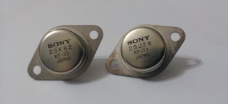
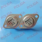
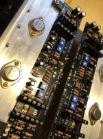
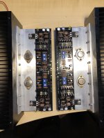
First image is from circuitdiy.com, a legit seller (sold out long time ago), and second image is from the ebay ad. Note the difference in fonts. The font of "SONY" in the genuine article is slimmer compared to the font of the ebay items.
The ebay VFETs don't appear genuine.
The ebay VFETs don't appear genuine.
Attachments
Anyone have an idea if these are legit?
1pair Audio Transistor SONY TO-3 2SJ18/2SK60 J18/K60 100% Genuine and New | eBay
I bought two of three times from that seller. Only fakes. The only genuine thing he has is the watermark on his pictures
Fakes on fleaBay
How can I determine if ones I bought a couple of years ago are fakes?
I bought two of three times from that seller. Only fakes. The only genuine thing he has is the watermark on his pictures
How can I determine if ones I bought a couple of years ago are fakes?
You can test them. A real SIT with the Gate and Source tied together will conduct
current Drain to Source that will be very proportional to the voltage.
Thanks. Exactly the info I needed
Anyone have an idea if these are legit?
1pair Audio Transistor SONY TO-3 2SJ18/2SK60 J18/K60 100% Genuine and New | eBay
Legit verified parts available, if you need them for vintage Sony TA amplifiers repairs
or new DIY build https://www.diyaudio.com/forums/swap-meet/355130-fs-sony-fets-2sk60-2sj18.html#post6220249
Best regards
")
Of historical interest, I have a small collection of 2SK60 2SJ18 that belonged to
Jim Bongiorno. I made a channel with a pair quite a long time ago, and I thought
the results were comparable - You can use them without modification in the DIY
push pull circuit.
Since the 2SK82 has two die in the package and some of the numbers are doubled
on the data sheet, I speculate that the 2SK82 might have two of the 2SK60 die,
similarly for the P channel versions.
HELP! Is my 2SJ28 Bad?
Thanks Dennis and to anyone. I've managed to test the 4 VFETs that I bought with a kit (seller of an unwanted project so the VFETS were mounted and soldered in place, and removed):
I've tested the VFETs in both ways (as per Sony Service Bulletin & by having them wired in a testing circuit). Sony guide:
https://solidstateamps.files.wordpress.com/2014/02/sony_service_bulleting_62.jpg
https://www.diyaudio.com/forums/att...-2-a-b5c6e185-9ae5-47ae-afac-74e96d4c88e0-jpg
ALL of them show between 1 to 1.3 ohms between S-D, and both S-G & D-G under diode test were normal (you probe 1 way to show nothing on the multimeter and reverse the test leads to show current going the other way). No problems here. However when doing the bench test wiring the VFET in circuit, i've got 1 outliar VFET:
In circuit test I used 2 x 9V batteries in series to form the bias gate voltage, and a lab power supply for the mains 19V voltage. https://www.diyaudio.com/forums/att...7078531-sony-vfet-amplifier-2-a-vfet-test-gif
https://www.diyaudio.com/forums/att...t-amplifier-2-a-vfet-20test-lab-batteries-gif
Both 2SJ28 have the same KF33 rank code: (A & B)
For 'A' I had instant conductivity at the lowest setting in the slide pot. It did not matter what current level I set the lab power supply at, it would instantly hit the maximum current draw. The voltage read out also would sag for eg. 1A would sag down to 6V and when I slid the pot, the voltage would go lower. This was kinda meaningless to measure the VGS but when I could, @ 0.8A the VGS was 10.8V. When I set the max current at 1A, I had a VGS of 10.32V.
For 'B' I had a normal result. No current shown until I had the slide pot over half way until I get a current reading at 0.5A with the VGS of 6.13V (the 1 ohm resistor was at 0.5V across the resistor). I also did another reading at 1A with VGS of 5.3V.
Both 2SK82 have the same KD33 rank: (C & D)
For 'C' again like in 'B', no current shown at start. Slide the pot until conduction started, went to 0.5A to note VGS of 6.19V, went to 1A and VGS of 5.13V
For 'D' no surprises. At 0.5A VGS of 6.60V and at 1A, VGS of 5.60V
So it seems VFET 'A' may be bad? It would not stop conducting once I applied the +19 from the lab power supply. Yet out of the testing circuit the S-D ohm reading and diode tests were all good.
Open to any recommendations... am I on the hunt to find another 2SK82? How about the rank code KF33 marking if they are required?
@Super_BQ: Here's the article for reference:
http://www.firstwatt.com/pdf/art_sony_vfet_pt1.pdf
As Bones13 mentioned, the power supply for CSX1 is more complicated that the
usual FW one.
For testing, you might want to try this schematics from post #209:
https://www.diyaudio.com/forums/pass-labs/276711-sony-vfet-amplifier-2-a-21.html#post4392065
It looks like one of your 2sk82 has the marking. Try wiring up the circuit for 2sk82
with the vfet heat sinked and start with the pot adjusted so the gate voltage is at -19V.
Monitor the voltage across the 1 ohm resistor for current. At -19V you shouldn't
see current. Gradually increase the gate voltage (moving towards zero) at some
point you the VFET should start conducting. See if you can gradually
increase the current to say 0.5A.
The current to gate voltage should follow a curve like the sample
attached.
Thanks Dennis and to anyone. I've managed to test the 4 VFETs that I bought with a kit (seller of an unwanted project so the VFETS were mounted and soldered in place, and removed):
I've tested the VFETs in both ways (as per Sony Service Bulletin & by having them wired in a testing circuit). Sony guide:
https://solidstateamps.files.wordpress.com/2014/02/sony_service_bulleting_62.jpg
https://www.diyaudio.com/forums/att...-2-a-b5c6e185-9ae5-47ae-afac-74e96d4c88e0-jpg
ALL of them show between 1 to 1.3 ohms between S-D, and both S-G & D-G under diode test were normal (you probe 1 way to show nothing on the multimeter and reverse the test leads to show current going the other way). No problems here. However when doing the bench test wiring the VFET in circuit, i've got 1 outliar VFET:
In circuit test I used 2 x 9V batteries in series to form the bias gate voltage, and a lab power supply for the mains 19V voltage. https://www.diyaudio.com/forums/att...7078531-sony-vfet-amplifier-2-a-vfet-test-gif
https://www.diyaudio.com/forums/att...t-amplifier-2-a-vfet-20test-lab-batteries-gif
Both 2SJ28 have the same KF33 rank code: (A & B)
For 'A' I had instant conductivity at the lowest setting in the slide pot. It did not matter what current level I set the lab power supply at, it would instantly hit the maximum current draw. The voltage read out also would sag for eg. 1A would sag down to 6V and when I slid the pot, the voltage would go lower. This was kinda meaningless to measure the VGS but when I could, @ 0.8A the VGS was 10.8V. When I set the max current at 1A, I had a VGS of 10.32V.
For 'B' I had a normal result. No current shown until I had the slide pot over half way until I get a current reading at 0.5A with the VGS of 6.13V (the 1 ohm resistor was at 0.5V across the resistor). I also did another reading at 1A with VGS of 5.3V.
Both 2SK82 have the same KD33 rank: (C & D)
For 'C' again like in 'B', no current shown at start. Slide the pot until conduction started, went to 0.5A to note VGS of 6.19V, went to 1A and VGS of 5.13V
For 'D' no surprises. At 0.5A VGS of 6.60V and at 1A, VGS of 5.60V
So it seems VFET 'A' may be bad? It would not stop conducting once I applied the +19 from the lab power supply. Yet out of the testing circuit the S-D ohm reading and diode tests were all good.
Open to any recommendations... am I on the hunt to find another 2SK82? How about the rank code KF33 marking if they are required?
Just to be sure that there was no mistake in your test of your 'A' 2SJ28, do the test again. Double check your circuit polarities before applying power.
First, turn the pot so that Vgs is at its maximum. That would be approximately 10/14.7 x 18V= 12.2V. Measure Vgs to confirm. Then turn on Vds=-19V (set to max 1A) and measure the voltage across the 1R resistor. If it measures 1V and Vds also sags as you had mentioned previously, then that is not good as the 2SJ28 is shorting.
First, turn the pot so that Vgs is at its maximum. That would be approximately 10/14.7 x 18V= 12.2V. Measure Vgs to confirm. Then turn on Vds=-19V (set to max 1A) and measure the voltage across the 1R resistor. If it measures 1V and Vds also sags as you had mentioned previously, then that is not good as the 2SJ28 is shorting.
Just to be sure that there was no mistake in your test of your 'A' 2SJ28, do the test again. Double check your circuit polarities before applying power.
First, turn the pot so that Vgs is at its maximum. That would be approximately 10/14.7 x 18V= 12.2V. Measure Vgs to confirm. Then turn on Vds=-19V (set to max 1A) and measure the voltage across the 1R resistor. If it measures 1V and Vds also sags as you had mentioned previously, then that is not good as the 2SJ28 is shorting.
Yes had done the test 3 times. First instance was at my neighbour place as he has a pretty nice bench table setup electronic repairs. The next day I tested it 2 more times at my place to confirm the problem with VFET 'A'. In sequence, I also retested Vfet 'B' to confirm my circuit was not setup wrong (with no issues with 'B' Vfet)
The voltage sagged all the way down once I made main power connection (battery supply always on). Yes I recall measuring around 12V with the pot all the way 1 end and adjusting the pot did nothing as going 1 end, the voltage would sag even more (ie 4v to like 2v or less).
Have a hook from a member here willing to sell a 2SJ28 with the same ranking code. His tested Vgs was slightly lower than my working 2SJ28 with the same ranking code (6.42v vs 5.3v on mine - though I was testing at 19V while he tested all his VFETS at 20V). Should not matter as i'm only using single complementary pairs per channel.
The lesson learned? I do believe everyone should test their vfets before going into this project.
Rumor says it that Mr Pass is working on another DIY VFET project to be released?
Same problem? different day
Did you get anywhere with this? Boards are in stock and I may recently have murdered a TA-5650 Which leaves me 2.5 pair Vfets (and a perpetual feeling of failure)
*wish* I really would love an idiots guide to using these boards with the baby transistors. It's SO stressful knowing they can't be replaced that it's not fun anymore.
OK at 100 out if 400 pages in I may have missed it but I'm still trawling through the 'is this genuine' posts
Andy
Ahh i see, thank you Rodeodave and ZM, so 2sk60/2sj18 are exact drop-in replacement for 2sk82/2sj28 since they have the exact same pin out, the only caveat is lowering Iq to 30% to 50% as they only have single die vs dual die as in 2sk82/2sj28
Thank you so much for the prompt replies and advices.
-TD
Did you get anywhere with this? Boards are in stock and I may recently have murdered a TA-5650
Which leaves me 2.5 pair Vfets (and a perpetual feeling of failure)*wish* I really would love an idiots guide to using these boards with the baby transistors. It's SO stressful knowing they can't be replaced that it's not fun anymore.
OK at 100 out if 400 pages in I may have missed it
but I'm still trawling through the 'is this genuine' posts Andy
Everything from the VFET pt. 2 guide applies to the 2sk60/2sj18. Same resistors, same basic voltages. The only characteristic that's different is the current. You'd adjust for 0.5A through R32, which would mean 50mV drop instead of 100mV drop.
To characterize the 2sk60/2sj18 VFETs you'd have to use the attached circuit and measure Vgs for 0.25A over 1R and use that Vgs in the setup procedure.
It's really just the different output devices and their specific Vgs (and 0.5A bias).
To characterize the 2sk60/2sj18 VFETs you'd have to use the attached circuit and measure Vgs for 0.25A over 1R and use that Vgs in the setup procedure.
It's really just the different output devices and their specific Vgs (and 0.5A bias).
Attachments
Thanks
Thanks @Rodeodave
Boards bought from the store - and now we wait or in my case read the rest of this thread at the very least
Again, really appreciate the response. I'm not really enjoying the instant component death side of Vfets. But am enjoying the results so far on the working (and refurbished) 5650...
Best regards
Andy
Thanks @Rodeodave
Boards bought from the store - and now we wait
or in my case read the rest of this thread at the very least Again, really appreciate the response. I'm not really enjoying the instant component death side of Vfets. But am enjoying the results so far on the working (and refurbished) 5650...
Best regards
Andy
I'm convinced VFETs are actually harder to kill than mosfets. They're not overly susceptible to ESD damage, no flimsy legs to bend or break, and most of all, a virtually zero temperature coefficient. The latter means that the current for a given bias won't run away when the part gets hot, which is why we generally don't see source resistors in the VFET designs.
There is of course the huge caveat that they're normally-on components that will definitely go up in smoke if you apply some drain-source voltage without an appropriate gate-source voltage present. But if that Vgs is there, they're pretty sturdy parts.
Good luck with your build, keep us posted!
There is of course the huge caveat that they're normally-on components that will definitely go up in smoke if you apply some drain-source voltage without an appropriate gate-source voltage present. But if that Vgs is there, they're pretty sturdy parts.
Good luck with your build, keep us posted!
Quite a few Vfets don't have a high dissipation rating. the Sony parts for example
are typically 60 watts or so, the SIT-1 transistor about 50 watts. For those, I keep
it at 30W or below.
The big Tokin parts get up to something like 3 KW, although the biggest I have on
the shelf is a mere 1 KW.
are typically 60 watts or so, the SIT-1 transistor about 50 watts. For those, I keep
it at 30W or below.
The big Tokin parts get up to something like 3 KW, although the biggest I have on
the shelf is a mere 1 KW.
Everything from the VFET pt. 2 guide applies to the 2sk60/2sj18. Same resistors, same basic voltages. The only characteristic that's different is the current. You'd adjust for 0.5A through R32, which would mean 50mV drop instead of 100mV drop.
To characterize the 2sk60/2sj18 VFETs you'd have to use the attached circuit and measure Vgs for 0.25A over 1R and use that Vgs in the setup procedure.
It's really just the different output devices and their specific Vgs (and 0.5A bias).
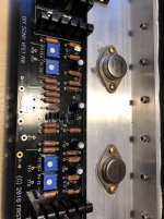
I made several units with k82/j28 with standard black boards, first two were from original kits, others with vfets from devastated N88 amp (one holds 4 pairs). Now I decided to go with yamaha's k76/j26. First run with lab PSU was very promising - sound is more "meaty" and "solid". An there's nothing special about Vgs and selection - just went by conventional route - frontend biasing, then put vfets in, adjusting each to consume equal current so to get both to consume 800-900ma in total at idle.
Attachments
- Home
- Amplifiers
- Pass Labs
- Sony VFET Amplifier Part 2