See page 11 of the DIY Sony VFET article:
"Practically speaking, you should not try to make this amplifier with rail voltages below 20 volts, and above 32 volts."
You'll have to bring down the voltage feeding the frontend somehow. It would also bring the TL431 fairly close to their maximum rating.
"Practically speaking, you should not try to make this amplifier with rail voltages below 20 volts, and above 32 volts."
You'll have to bring down the voltage feeding the frontend somehow. It would also bring the TL431 fairly close to their maximum rating.
I suppose I could bring a SIT-3 to BAF....
That’s it, I’m coming!

Hi Papa and everyone !
i have some vfet j18 / k60, can i use this schematic? What do I need to change to suit the vfet I have?
Thanks you
test them for Ugs , at 24Vd-s and Iq 1A
Hi everyone,
I'm finishing a pair of bridged Vfet monoblocks and I'm wondering whether I should un-ground both R4 resistors and attach them together, or just leave them to ground? I seem to remember reading a post from Nelson suggesting to tie them together, but I cannot find it again.
I'm currently adjusting the FE bias; will attaching both R4 together significantly change the adjustments? (I wouldn't think so, but I prefer asking rather than risking something)
Thank you!
Paul
Sony VFET bridged-differential switch
As you can see above, I've implemented a balanced-differential switch to my monoblocks.
It can be switched even with amp is power on.
I can't hear too much difference, but my hearing is far from perfect.
copper rod is good enough , if speaker wire coming to negative connector is fat enough
regarding bridging - you want to simply bridge them ( feeding balanced signal etc.) or you want to make them truly differential ?
in case of later - you need pulling both R4s from ground and connect their ends together (in series)
of course , observing DC offset tendencies is a must
As you can see above, I've implemented a balanced-differential switch to my monoblocks.
It can be switched even with amp is power on.
I can't hear too much difference, but my hearing is far from perfect.
Motorboating...
Hello, I built the Vfet (diyaudio store version with a single output pair /channel) and I like it very much, but I have some motorboating-issue.
I noticed it only after a week of use when I had my ear close to the woofer of my speaker. Attached a recording of it, first right channel and then left channel, in between some silence. As can be heard: frequency changes a bit over time, there are different signals on top of each other and frequency is clearly different from on channel to the other.
The signal you hear is of less quality than from my speakers, as I used an active monitor (ADAM A3X, directly on the output of my amplifier) and recorded it with my cellular phone on low resolution. The volume of the A3X is set to maximum, that would be 14dB amplification. As a test, I disconnected even the speaker cables and inputs, it has no effect on the motorboating...
After some reading, I think it might be the power supply...
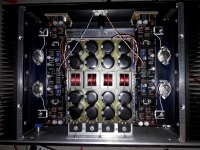
I have a custom audio transfo with 4 outputs and the powersupply is fully separated between left and right. On the picture you can see I used some Coilcarft common-mode chokes... I saw them once used in an AKSA powersupply and had some samples lying around => DCR is about 0,2 Ohms(per line of each phase). So I have for each phase 30mF + choke + 30mF...
My plan was to short the line of each phase that would get connected to gnd... So in the end I would have a regular 20mF + 0,2Ohm + 20mF CRC per fase (The core will be far saturated with the DC, if not already the case). If that doesn't work, I would remove these CMchokes and put regular 0,2Ohm resistor instead for a regular CRC, after that... I don't know..
Any idea's that would get me quicker to a solution?
Yes, it is a very compact construction for the Vfet.. but temps are acceptable I believe. Air-temp in the case is around 35°C with everything closed and the heathsinks <45°C (according to Nelsons calibration nomenclature, less than Blimey hot).
Hello, I built the Vfet (diyaudio store version with a single output pair /channel) and I like it very much, but I have some motorboating-issue.
I noticed it only after a week of use when I had my ear close to the woofer of my speaker. Attached a recording of it, first right channel and then left channel, in between some silence. As can be heard: frequency changes a bit over time, there are different signals on top of each other and frequency is clearly different from on channel to the other.
The signal you hear is of less quality than from my speakers
, as I used an active monitor (ADAM A3X, directly on the output of my amplifier) and recorded it with my cellular phone on low resolution. The volume of the A3X is set to maximum, that would be 14dB amplification. As a test, I disconnected even the speaker cables and inputs, it has no effect on the motorboating...After some reading, I think it might be the power supply...
I have a custom audio transfo with 4 outputs and the powersupply is fully separated between left and right. On the picture you can see I used some Coilcarft common-mode chokes... I saw them once used in an AKSA powersupply and had some samples lying around => DCR is about 0,2 Ohms(per line of each phase). So I have for each phase 30mF + choke + 30mF...
My plan was to short the line of each phase that would get connected to gnd... So in the end I would have a regular 20mF + 0,2Ohm + 20mF CRC per fase (The core will be far saturated with the DC, if not already the case). If that doesn't work, I would remove these CMchokes and put regular 0,2Ohm resistor instead for a regular CRC, after that... I don't know..
Any idea's that would get me quicker to a solution?
Yes, it is a very compact construction for the Vfet.. but temps are acceptable I believe. Air-temp in the case is around 35°C with everything closed and the heathsinks <45°C (according to Nelsons calibration nomenclature, less than Blimey hot).
Attachments
Last edited:
Yes, 4 independent phases, joining at amp boards.. (2 phases to each board) so each amp board has its own "star gnd" and without source everything is 100% split.. I could unsolder the two bridges ofone channel to see if the motorboating goes away...
silly to ask , but just in case - you have GND established , same as pos and neg rails , only after the choke ?
"after" means - on load side.....
- Home
- Amplifiers
- Pass Labs
- Sony VFET Amplifier Part 2