Pass DIY Addict
Joined 2000
Paid Member
Is it necessary to mount the Fets on a heat sink for this?
After only 20-30 seconds with 20v applied, the VFets get hot enough that they are difficult to handle. I would recommend mounting them to do any testing/measuring.
Hi, I posted this on the "other" build thread, not realizing it had split off.
Question: I have one of these amplifiers pre-built, but with two devices (VFET) per channel rather than the four of the circuit diagram. It has slots for the extra VFETs. I have read that the power goes up slightly and the distortion drops a bit if you use four per channel rather than two, but are there any other advantages i.e. longevity, less stress on the VFETs etc.to using the full complement of four VFETs per channel? It appears to be a drop in as long as the VFETs are matched and the board has the resistors for the extra pair. Any other precautions? I know the VFETs need to be closely matched.
Report Post
Claas,I drill a blind hole as a pilot hole (2.5mm for an M3 thread), and than hand-tap each hole with three consecutive tappers that get finer with each one ... it can even be slightly meditative (Zen-like) ...
Where did you get the three consecutive tappers?
I would love to be meditating rather than stressing! Just finished my first 12, but with a different thread and need to switch.
Thanks in advance,
Scott
Hi Scott,
I purchased this set of metric thread cutters years ago:
Mannesmann Thread Cutting Tool Set (32 Pieces): Amazon.de: Business, Industry & Science
Works very well.
The above is from Amazon Germany. The U.S. Amazon has it only as an import:
Amazon.com: Mannesmann Thread Cutting Tool Set (32 Pieces) by Br 1der Mannesmann: Home Improvement
I find that kind of expensive, more than twice the price the set costs in Germany. Maybe it is less expensive to have it shipped from Amazon Germany to the U.S. ?
On the other hand, a cursory look through Amazon U.S. did not reveal any thread cutter set I would trust in terms of quality.
I bought the Brothers Mannesmann set over 7 years ago and have used it in a number of builds, mostly cutting aluminium (or aluminum, as you say west of the Atlantic), almost exclusively 3 mm and 4 mm sizes. No wear on the tools yet.
I believe the 3 consecutive grades (pre-cut, finer cut, finish) have a lot to do with the quality of the thread and the endurance of the tool.
On Amazon U.S., all sets I saw looked like single-cut style thread cutters at closer inspection. Those can work well for a through-hole, but not for blind holes.
I learned using the 3-piece thread cutting method as a boy from my father, who had a vocational education as an engine fitter.
I got myself a spray can of cutting fluid also that I use for drilling and thread cutting. I only hand-cut, always use cutting fluid, and if the cutter starts to develop resistance ("starts to bind"), then back off a few turns until it turns freely again, then go on.
Good luck and have fun !
Best regards,
Claas
I purchased this set of metric thread cutters years ago:
Mannesmann Thread Cutting Tool Set (32 Pieces): Amazon.de: Business, Industry & Science
Works very well.
The above is from Amazon Germany. The U.S. Amazon has it only as an import:
Amazon.com: Mannesmann Thread Cutting Tool Set (32 Pieces) by Br 1der Mannesmann: Home Improvement
I find that kind of expensive, more than twice the price the set costs in Germany. Maybe it is less expensive to have it shipped from Amazon Germany to the U.S. ?
On the other hand, a cursory look through Amazon U.S. did not reveal any thread cutter set I would trust in terms of quality.
I bought the Brothers Mannesmann set over 7 years ago and have used it in a number of builds, mostly cutting aluminium (or aluminum, as you say west of the Atlantic
), almost exclusively 3 mm and 4 mm sizes. No wear on the tools yet. I believe the 3 consecutive grades (pre-cut, finer cut, finish) have a lot to do with the quality of the thread and the endurance of the tool.
On Amazon U.S., all sets I saw looked like single-cut style thread cutters at closer inspection. Those can work well for a through-hole, but not for blind holes.
I learned using the 3-piece thread cutting method as a boy from my father, who had a vocational education as an engine fitter.
I got myself a spray can of cutting fluid also that I use for drilling and thread cutting. I only hand-cut, always use cutting fluid, and if the cutter starts to develop resistance ("starts to bind"), then back off a few turns until it turns freely again, then go on.
Good luck and have fun !
Best regards,
Claas
The first piece to build my vfet amplifier.
An externally hosted image should be here but it was not working when we last tested it.
Hi Class,
Thanks for all the information!
Great idea, but amazon.ge won't ship it to the U.S. :-(
But I will keep looking.
Thanks for the cutting tips, my father hardly knows which side of a screwdriver to use. I did start using oil after the first hole or two, and now after the first couple 360degrees, only cut a little before backing it out a bit. I have not tried your technique of cutting until it binds, but will try it.
And thanks for the amazon.us searching too!
Cheers,
Scott
Marra, thanks! That is so timely! I started a dry assembly today prior to soldering and found there was oil still in the tapped holes even though I have given the heat sinks a wash in soapy hot water, followed by a rinse...and was going to ask Claas how he dealt with it.
I was shaving wood match sticks and screwing them down into the holes! :-(
Thanks again!
I was shaving wood match sticks and screwing them down into the holes! :-(
Thanks again!
I usually go into the tapped hole with a bit of tissue paper and a toothpick.
After that, I screw a bolt into the hole “solo” and wipe off the remaining cutting fluid that still emerges. After that, I don’t bother with any possible remaining residue.
So far, could not detect any dilution of the goop I use with my Mica insulators when I removed the FETs after a few months.
After that, I screw a bolt into the hole “solo” and wipe off the remaining cutting fluid that still emerges. After that, I don’t bother with any possible remaining residue.
So far, could not detect any dilution of the goop I use with my Mica insulators when I removed the FETs after a few months.
Last edited:
Ah!
Very good point about the raised rim. I second wdecho in the importance of getting rid of that.
What I do there after I‘m finished with tapping is using a larger drill bit (say, 6-8 mm diameter for a 3 mm thread) for deburring. I just turn it between my fingers, no machine power. That way I get rid of the raised rim without scratching the heatsink around the hole.
Checking if the surface is flat / planar and no raised rim remaining:
I cautiously run a metal ruler edge-on across the surface and look if any light peeks through beneath it.
I don’t use a file, because I want a near-perfectly flat and smooth surface at the mounting area of the FETs, with no deep scratches.
So I smooth the heatsink surface with something like grade 1000 sandpaper (European term, don’t know if that perfectly translates, but basically very very fine). It‘s like polishing, and best done with wet sandpaper. So I can smooth out roughness in the anodized surface.
The guys with an automotive diy hobby probably know what I‘m talking about
Maybe we should start a mechanics-related thread
Best regards, Claas
Last edited:
Pass DIY Addict
Joined 2000
Paid Member
My approach to drilling / tapping / mounting output transistors is this:
1) drill the hole to be tapped
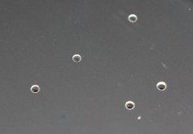
2) go up several sizes of drill bit and just "touch" the hole to remove the heavy portion of the deformation (first image)
3) tap the hole
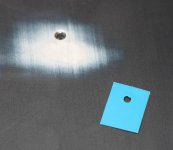
4) smooth with fine sandpaper and water/oil. Wrap sand paper around a square/flat block of metal so you don't further deform the surface of the sink - think of it as polishing like Claas indicated (second image)
5) pipe cleaners and/or air compressor is excellent for removing chips from tapped hole so they don't bind up the screw that goes in
1) drill the hole to be tapped
2) go up several sizes of drill bit and just "touch" the hole to remove the heavy portion of the deformation (first image)
3) tap the hole
4) smooth with fine sandpaper and water/oil. Wrap sand paper around a square/flat block of metal so you don't further deform the surface of the sink - think of it as polishing like Claas indicated (second image)
5) pipe cleaners and/or air compressor is excellent for removing chips from tapped hole so they don't bind up the screw that goes in
Attachments
Last edited:
Pass DIY Addict
Joined 2000
Paid Member
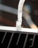
I'm not sure how well "pipe cleaner" translates, so here is another image. It is essentially a thin, twisted wire with cloth fibers protruding out in all directions like a long, thin brush. I fold it in half and run it up and down through the hole a few times. This method removes a surprising amount of chips from the newly tapped hole.
Attachments

Thanks guys, great tips!
I was thinking of doing a bit of counter-sinking but hadn't tried it, but didn't think of using it to removed the raised rim.
I removed the rim by using fine wet-dry sandpaper wrapped around the other heat sink...counter-sinking first would speed this step up quite a bit.
Eric, I'll pick up some pipe cleaners and use the air compressor that I didn't think about in the mean time.
Thanks again!
- Home
- Amplifiers
- Pass Labs
- Sony VFET Amplifier Part 2