As NP specified (TO-3P) couldn't be TO-246 a typo for TO-247?
Probably right. When I searched for TO-246 I came up with TO-247. I am not one to correct the king though. Might lose your head.
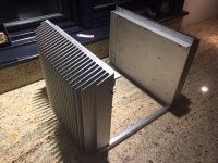
Will new brackets be 100% copy of old one?
For everyone's convenience, yes, at least in terms of the holes.
Ah sweet sound of success! After much torture I finally got the bad channel on my VFET squared away. I replaced all of the active components except Q7, Q8, Q9,and Q10. It was much easier to adjust and more stable. I kind of suspected the regs, but since I had it all torn apart went ahead and replaced everything.
i have it burning in in my garage now. First impressions are very good. I'm looking forward to comparing it to my M2. Thanks Nelson for the great design and to everyone for their help and advice.
Paul
i have it burning in in my garage now. First impressions are very good. I'm looking forward to comparing it to my M2. Thanks Nelson for the great design and to everyone for their help and advice.
Paul
You can find a BOM in post #2766: http://www.diyaudio.com/forums/pass-labs/276711-sony-vfet-amplifier-2-a-277.html#post4991406
For a working amp you'll need two pairs of 2SK82+2SJ28 VFETs.
For a working amp you'll need two pairs of 2SK82+2SJ28 VFETs.
Will add a few of observations:
Vishay Dale RN60/CMF60 resistors size are more perfectly fit for pcb resistors size between holes than RN55/CMF55.
Except R32 of course.
C3, C4, C5, C6 - 47uF 35V SILMIC II capacitor size between legs do not fit pcb size between holes. Could be used but with spaces. About ~2.2 mm difference.
And obvious Q5, Q6 - could be Toshiba 2SJ313/2SK2013 if you can find them. Same for Q1, Q2 - could be Toshiba 2SK170/2SJ74.
P.S.: I do not have PCB and components on hands yet.
You can find a BOM in post #2766: http://www.diyaudio.com/forums/pass-labs/276711-sony-vfet-amplifier-2-a-277.html#post4991406
For a working amp you'll need two pairs of 2SK82+2SJ28 VFETs.
Many thanks.
Fingers crossed my pair of 2sj28 are on their way.
just drill one new hole at capsWill add a few of observations:
C3, C4, C5, C6 - 47uF 35V SILMIC II capacitor size between legs do not fit pcb size between holes. Could be used but with spaces. About ~2.2 mm difference.
 diy's...
Single-ended Sony VFETs are in process. At the moment obtaining bracket quotes.

Hi Nelson,
I have interpreted this message as meaning "there will be a SE version" design. Did I miss a post about it or should I be patient and go make a snowman
 in the mean time?
 I have obtained two p-VFETs .
Very curious.
albert
Aleph J/Sony Vfet 2 combo amp
Hi all.
I have a question regarding the possibility of building these two amps into one chassis using one power supply. I was thinking of installing a channel of each per side, using the same power supply, and operating either one amp or the other by switching between them prior to power up. I have the stuffed boards and all required parts for an Aleph J build using the DIY Audio power supply board and the normal 18V transformer for it. I have an oversized DIY chassis that will easily fit one channel of the PCB board of the Aleph J, and one bracket for the Sony Vfet and its PCB, on each side of the amp. I would not operate them at the same time. It is too expensive to source an appropriate chassis in my neck of the woods, and I would much prefer to build both into one chassis rather than source out another and pay for it.
The only issues that I can see are that 24 Volts may not be enough for the Vfet amp, and the other is what might happen to the amp that is off, when the other one is on, with respect to heat. I use very efficient speakers, so I don't mind losing a few watts in output from the Vfet amp, if that helps to make it work. Any insight or advice would be much appreciated.
cascode input LTP in Aleph J , and you're good with higher rails ; keep dissipation on bay , no more than 35W per IRFP
Dodo amp will endure heat same as sleeping Cat
switching between amps - best to arrange with some sort of heavy shorting (multipoint) plug inside an amp , in a way that one plug is moving between two sockets , so you cannot easily make some mistake
don't forget that speaker output node also need to be switched , meaning Dodo amp speaker output must be floating/not connected to live amp
Last edited:
There is no real issue with building a 24VDC version of the VFET amp. I have built mine with +/-24VDC supplies and have it running now for close to a year. It's actually paired up with a mini Aleph J in biamping setup: http://www.diyaudio.com/forums/pass-labs/276711-sony-vfet-amplifier-2-a-post4987426.html
You will have to adjust R15 and R16 for the lower rail voltages. See the last page of the DIY Sony VFET article.
I don't see any real problem with running only one amp at a time. Components of the amp that's off will age slightly faster as compared to them being at room temperature in an amp with its own enclosure while being off, but that's about it I guess.
How will you be switching the DC voltage between the circuits? Switching DC at large currents is not entirely trivial iirc.
Thanks for the info! It's great that I can use one power supply and chassis for both, assuming that I don't use them at the same time. With respect to switching between them, I was thinking of an on-off main power switch connected to the power supply, and an on-off-on switch to go from the power supply to the amps. I will probably use a separate on-off-on switch for the speaker outputs from the amps. I could also combine the amp selector and speaker selector on-off-on switches, but having the DC selector and speaker selector on the same switch worries me. Does this make sense?
use 6 pole female connectors on back of the case - one for amp one , one for amp two
organize 6 poles as 3 pairs - one for positive rail , one for negative rail , one for speaker rail
use male plug , then just make shorts between mentioned pairs ;
when you want amp one to work - plug the plug in connector one
or for amp two , just move it to connector two
no need to switch inputs
sorry , I'm lazy to make a sketch
Zen Mod: Thanks. Using male to male jumper cables, and females chassis plugs makes more sense than switches in many ways, but I worry about myself, or someone else, plugging them in wrong if they are all compatible. Maybe barrel power connectors like the ones used on the end of wall wart transformers and something not compatible for the speakers?
I realized that I had posted a photo of the partially assembled chassis, showing the heat sinks, in the big Aleph J thread. I found the photo, and I had posted it in September 2015. That's more than two years ago! I fell into a two year vacuum tube hole. Time to finish off the Aleph j project, and do the Vfet one at the same time. Two birds with one stone....
Attachments
- Home
- Amplifiers
- Pass Labs
- Sony VFET Amplifier Part 2