Correct. You should aim for 28 Volt after rectifier. So 22Volt transformer.
22 will give about 29.5 after rectification. How much voltage sag can we expect when the power suppl y is loaded with the heavy bias?
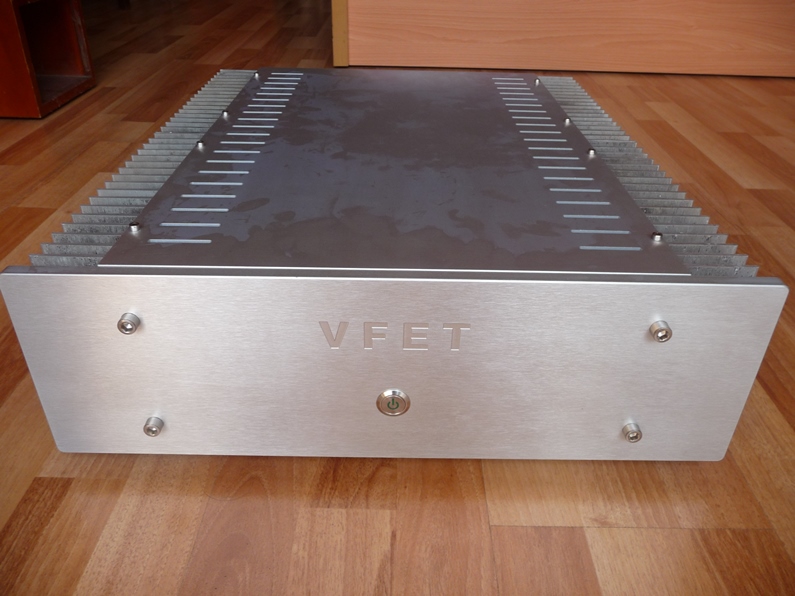
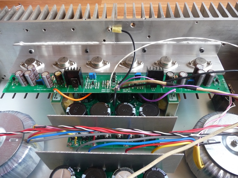
I upgraded my Sony VFET part 2 with:
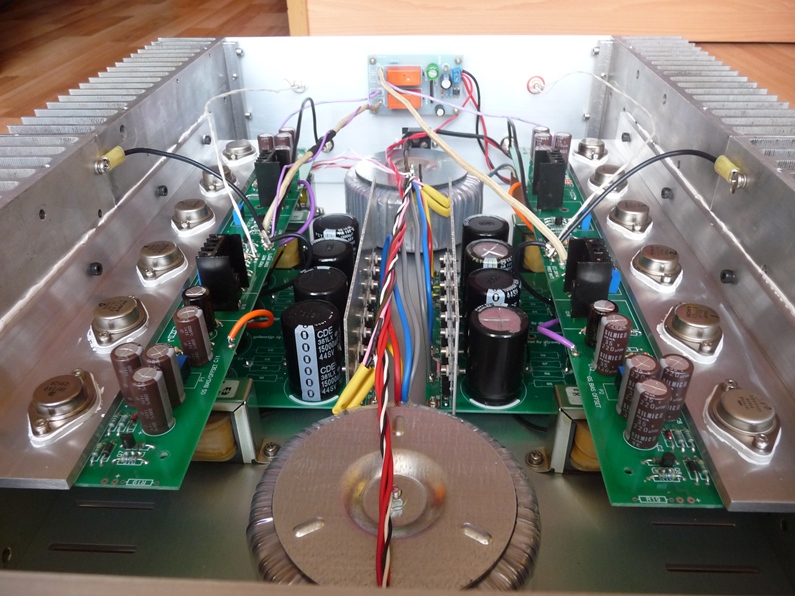
+ Double power supply
+ Replace some resistors in the signal path with tantalum non magnetic
+ C5/C6 with Rubycon BG FK serie
+ Remove Z3/Z4
+ Better wire for interconnect
+ TO-3 package regulation (IRF240/IRF9240)
+ New chassic without fan on the heatsink
The result: the sound was good and now is better so much
I upgraded my Sony VFET part 2 with:
+ Double power supply
+ Replace some resistors in the signal path with tantalum non magnetic
+ C5/C6 with Rubycon BG FK serie
+ Remove Z3/Z4
+ Better wire for interconnect
+ TO-3 package regulation (IRF240/IRF9240)
+ New chassic without fan on the heatsink
The result: the sound was good and now is better so much
Hi,
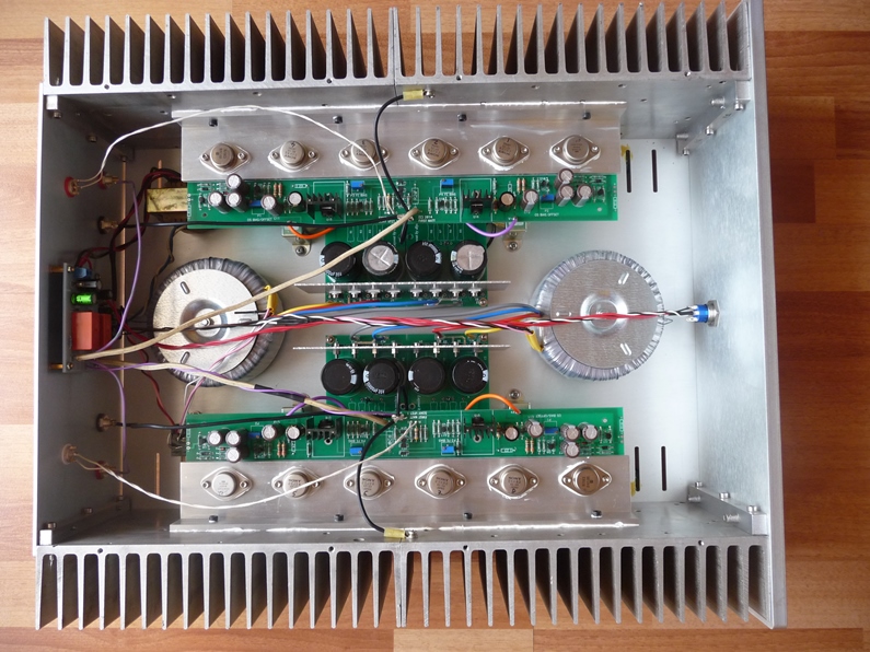
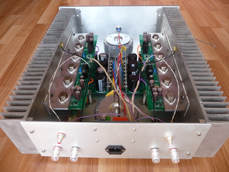
I saw you have 2 extra small transformers per channel under the amp board and a small circuit board at the back plate, what are they for ?
What do you meant by "TO-3 package regulation (IRF240/IRF9240)" ?
Very nice built.
Thanks
My amp have 4 chokes Hammond 156B for DC filter. You saw the loudspeaker protection on the back panel and one small transformer supply 24VACHi,
I saw you have 2 extra small transformers per channel under the amp board and a small circuit board at the back plate, what are they for ?
What do you meant by "TO-3 package regulation (IRF240/IRF9240)" ?
Very nice built.
Thanks
I used all TO-3 case transistor beside vfets for good view.
Last edited:
I upgraded my Sony VFET part 2 with:
...
+ Replace some resistors in the signal path with tantalum non magnetic
...
+ Remove Z3/Z4
...
The result: the sound was good and now is better so much
very well done job! my best wishes!
just few question: which resistors exactly in the signal path have you replaced? why removing the Z3/Z4? and no switch for changing between global/local feedback?
Dear Nagini, Buona sera amico.
Fantastic work, incredible finish, all DIY!
One question:
Does produce it much heat with this chassis?
I estimate the sizes of your amp, but, shall you specify them?
Thanks in advance and again, congratulations.
You are the builder I dreamed to be!!
Fantastic work, incredible finish, all DIY!
One question:
Does produce it much heat with this chassis?
I estimate the sizes of your amp, but, shall you specify them?
Thanks in advance and again, congratulations.
You are the builder I dreamed to be!!
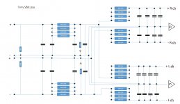
One transformer - dual supply?
If you have one transformer with dual secondaries, 2 x 22Vac, each secondary connected to a bridge rectifier, and then the rectifiers connected to the cap banks, is it then possible to make a rCRC + dual rCRC powersupply? The left and right channel will then have separate capasitors for the last part of the powersupply, but have do you go about for audio and supply "ground" and for return currents to the transformer windings. Maybe not the best solution? I tried to make a sketch to explain:
If you have one transformer with dual secondaries, 2 x 22Vac, each secondary connected to a bridge rectifier, and then the rectifiers connected to the cap banks, is it then possible to make a rCRC + dual rCRC powersupply? The left and right channel will then have separate capasitors for the last part of the powersupply, but have do you go about for audio and supply "ground" and for return currents to the transformer windings. Maybe not the best solution? I tried to make a sketch to explain:
Attachments
Thanks all!
+ I upgraded R21/R41/R42/R1/R2/R3/R4 with tantalum resistors, others are Takman metal film (REY).
+ Papa removed all zeners for protect VFETs and MOSFETs regulator, I just removed zeners protect VFETs because I think it necessary
+ I and all my friends have the same idea, that is the sound without global feedback is better so I removed the switch
+ The new heatsink is expensive and must pay the shipping cost so I try to find the second hand heatsink that used in a industry machines and because of that I can't active to calculate the size, I must follow the size of heatsink that I found. After combine 4 heatsinks, my amp dimension: 520mm (D) x 135mm (H); that is the size I must fix and just calculate the wide. This is the original VFET P2 so Papa said the bias is 1A to 1.5A, my amp running at 1.25A at about 50 degrees (Celcius)
+ I upgraded R21/R41/R42/R1/R2/R3/R4 with tantalum resistors, others are Takman metal film (REY).
+ Papa removed all zeners for protect VFETs and MOSFETs regulator, I just removed zeners protect VFETs because I think it necessary
+ I and all my friends have the same idea, that is the sound without global feedback is better so I removed the switch
+ The new heatsink is expensive and must pay the shipping cost so I try to find the second hand heatsink that used in a industry machines and because of that I can't active to calculate the size, I must follow the size of heatsink that I found
. After combine 4 heatsinks, my amp dimension: 520mm (D) x 135mm (H); that is the size I must fix and just calculate the wide. This is the original VFET P2 so Papa said the bias is 1A to 1.5A, my amp running at 1.25A at about 50 degrees (Celcius)andRookie, take a look at the 2012 F6 talk over at FIRST WATT ARTICLES which is showing such a PSU.
...
+ I upgraded R21/R41/R42/R1/R2/R3/R4 with tantalum resistors, others are Takman metal film (REY).
+ Papa removed all zeners for protect VFETs and MOSFETs regulator, I just removed zeners protect VFETs because I think it necessary
+ I and all my friends have the same idea, that is the sound without global feedback is better so I removed the switch
...
many thanks! enjoy the excellent amp!
andRookie, take a look at the 2012 F6 talk over at FIRST WATT ARTICLES which is showing such a PSU.
Thanks! I read that you could "split the RC networks out the each channel separately" but I am still not sure how to do it regarding ground and return currents to transformer secondary. I`ll try to do more search here and at the power supply section.
Moved the amp to my main system tonight. Sounding very good. Organic and relaxed from bottom to top. Wonderful vocals. Special sort of palpable authority on the low end. Me likey!
BK
Congratulations and thx for share your sound impressions.
I feel urgency to complete my diy builds now

I upgraded my Sony VFET part 2 with:
+ Double power supply
+ Replace some resistors in the signal path with tantalum non magnetic
+ C5/C6 with Rubycon BG FK serie
+ Remove Z3/Z4
+ Better wire for interconnect
+ TO-3 package regulation (IRF240/IRF9240)
+ New chassic without fan on the heatsink
The result: the sound was good and now is better so much
Oh Man that great build amplifier. Bravo !
Enjoy
Of course! That is the feel for anyone when they listen to the sound of this amp!Moved the amp to my main system tonight. Sounding very good. Organic and relaxed from bottom to top. Wonderful vocals. Special sort of palpable authority on the low end. Me likey!
BK
- Home
- Amplifiers
- Pass Labs
- Sony VFET Amplifier Part 2