k170/ j74 match for input stage
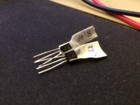
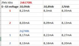
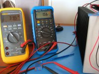
I have some jfet in my drawer from when I built my F5 some years ago. Two 2sj74BL and about 12 of the 2sk170BL. I wanted to see if I could use the two j74 and two of the k170 as matched pairs in the input stage of my VFET amp. By testing Idss at tree different voltages I found two pairs that are quite close to each other. I have been trying to read up on what is a match, but could you guys comment on if the pairs I found are close enough not to diminish the quality of the VFET amp. Compared to jfet pairs/quads on sale here at diyaudio.com I see that my two pairs are a bit apart on Idss.
I hope my notes are comprehensive.
Attachments
Soundhappy --
The LED are just blue with clear lenses, I have no idea the part number, I had a bunch of them in my box.
As for adjusting feedback, the operating points of the Vfet output devices is exact, I wouldn't suggest any adjustments unless Nelson says so.
andRookie --
Your Jfet are close enough to use. (they are actually pretty good match) The front-end bias pots will make up for any difference.")
The LED are just blue with clear lenses, I have no idea the part number, I had a bunch of them in my box.
As for adjusting feedback, the operating points of the Vfet output devices is exact, I wouldn't suggest any adjustments unless Nelson says so.
andRookie --
Your Jfet are close enough to use. (they are actually pretty good match) The front-end bias pots will make up for any difference.
Soundhappy --
The LED are just blue with clear lenses, I have no idea the part number, I had a bunch of them in my box.
As for adjusting feedback, the operating points of the Vfet output devices is exact, I wouldn't suggest any adjustments unless Nelson says so.
It was question about other brand or model resistors not blue LED
and they are not usual RN55 or CMF no magnetic Dale ??
I get interesting 2K1 and 320 R feedback resistors but yeah they are not precisely the same values but stay into ~ 10 % range.
I know Mr Pass study and find sweet spot and linearise frequency response by feedback loop and find optimal distorsion content so is better go close to his R values from schematic...is little flexibility ther or better not ?
Greetings
Oh!
I think the resistors are Yeago. Or Xicon.
Changes to resistors is not because of optimal distortion, but operating points of the Vfet - although the feedback is mainly into the front-end, it's still a global loop and may affect the outputs. I suggest getting an answer from Nelson.
I think the resistors are Yeago. Or Xicon.
Changes to resistors is not because of optimal distortion, but operating points of the Vfet - although the feedback is mainly into the front-end, it's still a global loop and may affect the outputs. I suggest getting an answer from Nelson.
2.5V at T18 (the output of the front end) should be much closer to 0V. Any
offset here will be deducted from the output swing, so you will clip at 2.5 V
earlier than you would like. A little DC here is OK.
All four pot adjustments are involved and have some influence on each other,
so you want to tweak the DC bias through the front end, the DC at T18, the
bias current in the output stage and the output DC. Do it in small baby steps,
iterating through all 4 pots so as to get it right.
Thank you, Nelson. Your pdf instructions at the end are clear about "checking and adjusting the other bias values as you go along", but I had neglected to go back and reset T18. Now I understand.
With some very careful work and multiple meters, I was able to get <2mV output stage offset and <40mV front end offset. All at terminal temp. I'm thrilled with that.
But wow, it was like balancing marbles on the head of a pin and one channel was more of a handful than the other. My trick was not to actually make perceptible turns, but to apply just enough pressure to deflect the trimmer mechanism and see what direction things were heading and then figure out which combination of trimmers got things to converge in the right direction and not opposite direction. A bit like a 3D puzzle. The single-turn units were quite a challenge!
BK
Attachments
Changes to resistors is not because of optimal distortion, but operating points of the Vfet - although
the feedback is mainly into the front-end, it's still a global loop and may affect the outputs.
I suggest getting an answer from Nelson.
I do test all resistors T points to see if they are in his ohm's range.
Thanks and have a nice sunday

Attachments
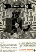
Interesting picture, Soundhappy. Telephone systems traditionally transmits the voice frequency band 300 Hz to 3400 Hz. Never place your crossover frequency in there!
Also, to reach up to 3400 Hz the sampling frequency 8 kHz were chosen. (And 8 bits.) The pro sample rate of 48 kHz is a multiple of 8 kHz as 16 and 24 bits also are multiples of 8 bits. To make the story short, 8 kHz 8 bits can be said to be one of the fundamentals of the universe.
Anyway, remember the part about the crossover frequency!
Regds
Interesting picture, Soundhappy
Yes R-K is interesting picture beacause Diy Vfet P2 power rate is 15 watt in 8 ohm's load
and Mr Pass use 25 watts two pairs vfet's for one channel version amp to play music on his Cathedrals
Audiophile Speakers Made in USA - No MDF
Efficient speakers & horns are the key to enjoy vfets
Bell Labs and Western Electric always show way of excellence and was the pioneer's
Yeah be funny project to make some dedicated crossover for smart phone if i call First Watt company
....just joke
My kindest regards
CoolNow go build your amp Soundhappy!
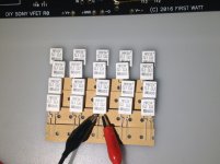
I am ready on work bench and match MPC74 Futaba 0.1 | 5 watts resistors
and the other interesting components is in shipping now

Lot's of fun !
Attachments
But wow, it was like balancing marbles on the head of a pin
If you're looking for 2 mV offset, yes it is. I usually bother above 20 mV.
I'd be up for dual mono Plitrons if a list is starting for them
What is Plitron price if group buy ?
Greetings
What is Plitron price if group buy ?
Greetings
I started a thread in the Group Buys section.
- Home
- Amplifiers
- Pass Labs
- Sony VFET Amplifier Part 2