Cantilope has gave his blessing allowing me to answer questions for him. Yes he did use the store PS boards. We both ordered the same parts for our amps together. I do not remember the exact brand of caps but they are nothing special, just good relatively inexpensive 15K uf brands. Tucked under the boards are 4 40uf motor run caps. If you have to know the exact ones I will have to go to my purchase order to find out.
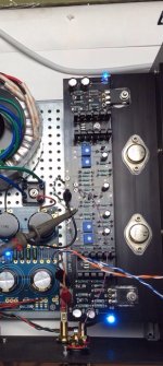
He did a tremendous job fitting two transformers and two PS into one case. He is the first I have heard that has built essentially mono V-fet amps. I will almost bet that Might Zen's build will be something similar if not monos. He took Zen's advice about the wire wrapping as well. Very professional neat clean looking build. Mine is an ugly box but she is sweet inside.
It looks really nice indeed!
I was just wondering about the dimensions of the capacitors, they can't be too tall or they will hit the amplifier boards.
For those who need transformers, how many of you would be interested in building it as dual mono? Could the store order the transformers from Plitron for either dual mono or stereo?
I'm wondering what the cost difference would be between the two.
I'd would be interested in transformers for the dual-mono version.
I know this has been discussed a bazillion times on other First Watt build threads, but I'm gonna ask it again:
Can the RN55 Vishay/Dale resistors be substituted for the CMF55 resistors that are in the current VFET BOM?
My understanding is that:
1) CMF55 resistors can have steel or copper leads, while the RN55 resistors are always copper leads.
2) CMF55 are rated 1/2 watt, while the RN55 are derated to 1/8 watt to meet military specs - otherwise they are very similar.
Thanks as usual!
Cappy - Of course you can use the RN55. They are my favorite resistor.")
@ 6L6
In Diy Vfet P2 build guide i see on the pcb's photo other light blue resistors...what is the brand or reference ?
Just curious i do my own way.

Greetings
oh... have i missed something? is the 6l6's build guide for diy-vfet p2 already online?@ 6L6
In Diy Vfet P2 build guide i see on the pcb's photo other light blue resistors...what is the brand or reference ?
Just curious i do my own way.
Greetings
oh... have i missed something? is the 6l6's build guide for diy-vfet p2 already online?
Oops sorry for precision i was write about few photos 6L6 share with us
from build guide preparation not finished official on line

Her is the photo with this turquoise clear blue R's..
Greetings
Attachments
Last edited:
ah.... ok . thanks!Oops sorry for precision i was write about few photos 6L6 share with us
from build guide preparation not finished official on line
Her is the photo with this turquoise clear blue R's..
Greetings
looking forward for 6l6 build guide !
looking forward for 6l6 build guide !
Me too + 1

Kindest regards
My amp is fully setup, burned in and has been making good music.
R32 and R5/R6 are all spot on. Device temps all seem similar. DC offset at the outputs is only 1-12mV at temp. All normal and good.
At this point is there any significance to T18 vs. gnd? One channel is ~125mV and the other is ~2.5V. The latter one has a marginally less stable DC offset at the output (but still under 12mV) in that it slowly drifts and seems more temp sensitive for example with the cover on/off, etc.
BK
My amp is fully setup, burned in and has been making good music.
R32 and R5/R6 are all spot on. Device temps all seem similar. DC offset at the outputs is only 1-12mV at temp. All normal and good.
At this point is there any significance to T18 vs. gnd? One channel is ~125mV and the other is ~2.5V. The latter one has a marginally less stable DC offset at the output (but still under 12mV) in that it slowly drifts and seems more temp sensitive for example with the cover on/off, etc.
BK
I really do not understand what you mean when you say T18 Vs gnd etc. If the worse DC offset is 12mv you have no worries. If your DC offset is too much you will hear it in your speaker turning on or turning off. Under 50mv is considered satisfactory.
Can't find CMF41.2K at Digikey for R15,R16.
Can I safely replace with CMF42.2K or CMF40.2K?
Thx
I answer myself
, I guess these will also do:Electronic Components and Parts Search | DigiKey Electronics
Sorry previous link missing part N°
MRS25000C4122FRP00 Vishay BC Components | Resistors | DigiKey
MRS25000C4122FRP00 Vishay BC Components | Resistors | DigiKey
The brackets are listed as well. They are needed when the SE V-fet design becomes available from our leader.
http://diyaudiostore.com/collections/accessories/products/to3-ums-compatible-chassis-brackets
Last edited:
At this point is there any significance to T18 vs. gnd? One channel is ~125mV and the other is ~2.5V.
2.5V at T18 (the output of the front end) should be much closer to 0V. Any
offset here will be deducted from the output swing, so you will clip at 2.5 V
earlier than you would like. A little DC here is OK.
All four pot adjustments are involved and have some influence on each other,
so you want to tweak the DC bias through the front end, the DC at T18, the
bias current in the output stage and the output DC. Do it in small baby steps,
iterating through all 4 pots so as to get it right.
- Home
- Amplifiers
- Pass Labs
- Sony VFET Amplifier Part 2