F7 simulation
Not built, but just simulated, see Installing and using ngspice - an opensource simulator and Installing and using ngspice - an opensource simulator. The schematic is taken from First Watt F7 review, the devices and resistor values from F5 and F6 simulation experience.
Not built, but just simulated, see Installing and using ngspice - an opensource simulator and Installing and using ngspice - an opensource simulator. The schematic is taken from First Watt F7 review, the devices and resistor values from F5 and F6 simulation experience.
Last edited:
If you want more OLG and power, just use GR grade JFETs and double-die MOSFETs.
But it is not a F7, because you have changed its distortion signature.
Like the J2, it is not about the lowest distortion, but a certain signature.
You can also argue that it is a music instrument, not an amplifier.
")
Patrick
But it is not a F7, because you have changed its distortion signature.
Like the J2, it is not about the lowest distortion, but a certain signature.
You can also argue that it is a music instrument, not an amplifier.
Patrick
@avdesignguru, if you haven’t tried the F7 with your WHAMMY yet, you should. I found the BA2018 very detailed as well but the WHAMMY seems to smooth things out just enough without sacrificing detail, imaging, or stage.
I tried my Whammy (with OPA1612) and found it smoother but sacrificed a small amount of detail, so I still prefer the BA2018. I also tried my B1K and find I also prefer the BA2018. I do reverse the loudspeaker leads when listening to the B1K to maintain signal chain polarity.
RE: BA2018 output devices, reading Dimitri Danyuk's "Build a Fully Balanced Transconductance Preamplifier" in this month's Audio Express, he said "I prefer the sound of transistors with large dies in circuits without overall feedback." So I thought I would replace the regular outputs I had originally installed with the optional large ones. I really can't hear much difference, so maybe that isn't critical in Wayne's circuit design. At least for my ears.
If you want more OLG and power, just use GR grade JFETs and double-die MOSFETs.
But it is not a F7, because you have changed its distortion signature.
Like the J2, it is not about the lowest distortion, but a certain signature.
You can also argue that it is a music instrument, not an amplifier.
Patrick
True about the distortion signature etc, I'm just trying something a little different! BTW what does OLG mean, pardon my ignorance! Oh the penny just dropped open loop gain!
Last edited:
@avdesignguru, if you haven’t tried the F7 with your WHAMMY yet, you should. I found the BA2018 very detailed as well but the WHAMMY seems to smooth things out just enough without sacrificing detail, imaging, or stage.
I use a Schiit Magni 2 Uber (has pre outs) to run my F7 rendition.Cost me just over $100.Its,small and has a very neutral sound signature,max gain of around 15db.I can't think of a better low cost unit for those who don't want to build their own pre amp.They now have 2 new ones,one discreet and one op amp version.
I tried my Whammy (with OPA1612) and found it smoother but sacrificed a small amount of detail, so I still prefer the BA2018. I also tried my B1K and find I also prefer the BA2018. I do reverse the loudspeaker leads when listening to the B1K to maintain signal chain polarity.
I think I need to give the BA2018 another listen then!
I also need to swap in the larger outputs. And I might try the Jensen signal transformer mod on the output while I’m at it. On the F7, I had been listening to the MoFo with BA3 preamp combo lately then switched back to the F7 clone. The soundstage on MoFo was huge, great for live music, orchestra, coral, etc. But there’s no contest, in my experience, for imagining and bass control. The F7 clone is so pinpoint, detailed and had full controlled bass. It’s such a good amp. Makes me wonder if the MoFo isn’t dialed in somehow.
Last edited:
Mathematical Analysis of the F7 Topology
The following has been approved for publication by Nelson.
Very generous of him.
Although Lynn has published extensively on the theory behind the “feedforward” act in various topologies in post #442, etc.,
I thought it might be interesting to see how those equations are derived from first principle. I hope that Nelson would not mind.
Disclaimer :
1. I shall only use the schematics posted by Nelson in post #1425.
2. All values presented here are pure speculation on my part and have nothing to do with reality.
3. The motivation is, hopefully, to help people to understand how the topology functions, and not to carbon copy.
4. I have no intension to build myself, so it is a pure theoretical study with no experimental verification.
The reason for the need to feed forward is that the output impedance is way too high otherwise, as mentioned by Nelson in the F7 Manual.
Since there is no free lunch, the penalty is higher distortion, as also mentioned by Nelson.
So before we can analyse the circuit, we need to have a good idea of the output impedance of the basis amplifier (as in the Profet).
One can easily set up a Spice model of the Profet circuit and determine the output voltage with different loads.
We did that with loads between 1R and 16R, and determined the Zo to be 1.6R.
This agrees well with Nelson’s figure of damping factor of 5 (when referenced to 8R load).
It was also mentioned that the output voltage does not change in the F7 even when the output has no load.
This is actually very useful in determining some resistor values.
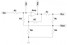
Referring to the theoretical schematics attached :
The Profet circuit is represented by an ideal operational amplifier (Amp) in series with an output impedance Zo.
The rest is pretty much according to post #1425.
To start with, assume an open circuit at the output, i.e. RL = ꝏ.
No current will flow throw R4 and Zo. Therefore Vsen = 0V.
And there is no voltage drop across Zo.
The output voltage VLo = Vin x R2 / (R1+R2) x (R7+R6) / R6
If we put R7 = 10 x R6 as in post #1425, but R1 = R2, then closed loop gain CLG = 5.5.
Quite close to 14.5dB in the F7 manual.
Assume now that the amplifier should have a near constant CLG, largely independent on the RL.
Also the range of RL should be between 1R and 16R.
The geometric mean is then 4R.
We shall use this as the design point.
Using the results from above, i.e. R1=R2 and R7 = 10.R6, Zo = 1.6, and RL = 4
the signal voltage at the Amp input
Vai = ½ x ( Vin + Vsen )
= [ Vin + Vao x R4 / (Zo + RL + R4) ] / 2
= [ Vin + 11 x Vai x R4 / (5.6 + R4) ] / 2
Rearranging,
Vin = Vai x (2 – 11 x R4 / (5.6 + R4))
= VLo / 4 x (5.6 + R4) / 11 x (2 – 11 x R4 / (5.6 + R4))
But we want to have the voltage across load
VLo = Vin x 5.5
Therefore, eliminating Vin in both equations,
2 x (5.6 + R4)/4 – 11/4 x R4 = 2
R4 = 0.36 ohm
The effective input impedance seen by the source, with a 4R load, can be calculated as follows :
For a certain input voltage Vin, ( VLo – Vsen ) = 5.5 x Vin.
Hence Vsen = 0.36 / 4 x 5.5 x Vin = 0.495 x Vin
Zin = (R1 + R2) / (1 – 0.495) = 3.7 x R1
Note that this value varies with RL. For 8R, e.g., Zin = 3.7 x R1.
If you wish the source to see a constant impedance, you should consider choosing a larger value for R1.
And then connect an additional resistor between Vin and Gnd to swamp the effect of R1, R2 and Vsen.
The exact values of R1, R2, R6, R7 will have a direct effect on the frequency response of the circuit.
But this is best determined in Spice simulations.
And of course, if you decide to change output devices (e.g. double die), or desired closed loop gain, etc. the actual numbers will change.
But the maths is the same.
QED.
Patrick
The following has been approved for publication by Nelson.
Very generous of him.
Although Lynn has published extensively on the theory behind the “feedforward” act in various topologies in post #442, etc.,
I thought it might be interesting to see how those equations are derived from first principle. I hope that Nelson would not mind.
Disclaimer :
1. I shall only use the schematics posted by Nelson in post #1425.
2. All values presented here are pure speculation on my part and have nothing to do with reality.
3. The motivation is, hopefully, to help people to understand how the topology functions, and not to carbon copy.
4. I have no intension to build myself, so it is a pure theoretical study with no experimental verification.
The reason for the need to feed forward is that the output impedance is way too high otherwise, as mentioned by Nelson in the F7 Manual.
Since there is no free lunch, the penalty is higher distortion, as also mentioned by Nelson.
So before we can analyse the circuit, we need to have a good idea of the output impedance of the basis amplifier (as in the Profet).
One can easily set up a Spice model of the Profet circuit and determine the output voltage with different loads.
We did that with loads between 1R and 16R, and determined the Zo to be 1.6R.
This agrees well with Nelson’s figure of damping factor of 5 (when referenced to 8R load).
It was also mentioned that the output voltage does not change in the F7 even when the output has no load.
This is actually very useful in determining some resistor values.
Referring to the theoretical schematics attached :
The Profet circuit is represented by an ideal operational amplifier (Amp) in series with an output impedance Zo.
The rest is pretty much according to post #1425.
To start with, assume an open circuit at the output, i.e. RL = ꝏ.
No current will flow throw R4 and Zo. Therefore Vsen = 0V.
And there is no voltage drop across Zo.
The output voltage VLo = Vin x R2 / (R1+R2) x (R7+R6) / R6
If we put R7 = 10 x R6 as in post #1425, but R1 = R2, then closed loop gain CLG = 5.5.
Quite close to 14.5dB in the F7 manual.
Assume now that the amplifier should have a near constant CLG, largely independent on the RL.
Also the range of RL should be between 1R and 16R.
The geometric mean is then 4R.
We shall use this as the design point.
Using the results from above, i.e. R1=R2 and R7 = 10.R6, Zo = 1.6, and RL = 4
the signal voltage at the Amp input
Vai = ½ x ( Vin + Vsen )
= [ Vin + Vao x R4 / (Zo + RL + R4) ] / 2
= [ Vin + 11 x Vai x R4 / (5.6 + R4) ] / 2
Rearranging,
Vin = Vai x (2 – 11 x R4 / (5.6 + R4))
= VLo / 4 x (5.6 + R4) / 11 x (2 – 11 x R4 / (5.6 + R4))
But we want to have the voltage across load
VLo = Vin x 5.5
Therefore, eliminating Vin in both equations,
2 x (5.6 + R4)/4 – 11/4 x R4 = 2
R4 = 0.36 ohm
The effective input impedance seen by the source, with a 4R load, can be calculated as follows :
For a certain input voltage Vin, ( VLo – Vsen ) = 5.5 x Vin.
Hence Vsen = 0.36 / 4 x 5.5 x Vin = 0.495 x Vin
Zin = (R1 + R2) / (1 – 0.495) = 3.7 x R1
Note that this value varies with RL. For 8R, e.g., Zin = 3.7 x R1.
If you wish the source to see a constant impedance, you should consider choosing a larger value for R1.
And then connect an additional resistor between Vin and Gnd to swamp the effect of R1, R2 and Vsen.
The exact values of R1, R2, R6, R7 will have a direct effect on the frequency response of the circuit.
But this is best determined in Spice simulations.
And of course, if you decide to change output devices (e.g. double die), or desired closed loop gain, etc. the actual numbers will change.
But the maths is the same.
QED.
Patrick
Attachments
Last edited:

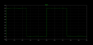
For a sanity check, we simulated a circuit based on the results from the previous analysis.
Input voltage is 1V, 1kHz.
Output voltage across load :
1R 5.37V
2R 5.39V
4R 5.40V
8R 5.41V
16R 5.41V
At 1W, 1kHz into 8R
H2 0.056%
H3 0.0013%
If R1=R2=3.9k (Zin~10k at 8R load), -3dB bandwidth ~ 1.3MHz
If R1=R2=39k, and input is connected to Gnd with a 11k resistor, -3dB BW ~ 130kHz
I guess that is not too far off.
Cheers,
Patrick

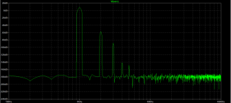
A couple of simulation results to compare with those in the manual.
Patrick
.
Cool!
Someone wants to know about a headphone version.
Even with 32R phones, 1.6R Zout is perfectly OK.
So there is no need for any feedforward.
i.e. a standard Profet with reduced bias will do fine.
But then with the same gain devices, the UTHAiM is, IMHO, a better circuit.
Patrick
Even with 32R phones, 1.6R Zout is perfectly OK.
So there is no need for any feedforward.
i.e. a standard Profet with reduced bias will do fine.
But then with the same gain devices, the UTHAiM is, IMHO, a better circuit.
Patrick
F2 exactly 0.05%, according to spec (1W 8R 1kHz).
Just by changing Vto of PMOS by 40mV.
QED.
Patrick
.
Sorry Patrick, I did not express myself correct, I did not mean the absolute value of h2 in relation to 1kHz signal.
But the relation of h2/h3 given in the F7 manual with a difference of around 10dB.
- Home
- Amplifiers
- Pass Labs
- First Watt F7 review