Anyone know if Kester 331 63/37 (low smoke) is OK?
Kester 331 Organic Core Solder 63/37 .031" 1 lb. Spool
I've never used anything but rosin core solder. The smell doesn't bother me. I used Radio Shack solder for years doing TV service. I wish they were still around. They were like a convenience store.
I also use Kester "44" core 60/40 and 63/37. Both are decent. Kimco sometimes has sales on Kester "44" 63/37 .031 for about $18 plus shipping.
I want to try Amerway solder from TEquipment. It's made in USA, only about $10 and it gets good reviews.
https://www.tequipment.net/Amerway/AM63.37.SPOOL.1LB/Solder-Wire/
posting tips that will benefit any of us who may find themselves in a similar position in the future.
That's why I do it, but I feel like I'm muddying up the thread.
The smell doesn't bother me
The fumes kill me.
 Buying the low smoke Kester today.
The solder fumes keep me from approaching projects and there's too many things I want to try.
Anyway, thanks for all the help!
Vince
The fumes kill me.
The solder fumes keep me from approaching projects and there's too many things I want to try.
Anyway, thanks for all the help!
Vince
One of these will help!
Fume Extractor
I am playing with my version.
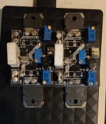
This PCB is very small, just 60×70mm.
Mine is smaller than yours

These are 42x33, built with recycled actives and a mix of SMD and TH resistors. Excuse the mess, haven't cleaned the boards up yet.
My sim was with 16V rails and low bias (around 650-700mA). As you can imagine I had to jump quite a few hoops to get everything to line up nicely at that low bias so decided to give up some loop gain.
I have only 12dB of it but since the rails are low I can just about max the amp out with 2Vrms. The sound is pretty good but the build is a way from completion.
I must fess up to using some ideas from the thread to put mine together, though both feedback loops run a little stronger (lower OLG due to lower transconductance) and there's a bit more degen on the input JFETs - so it's unlikely my application can be repeated. It is basically a nice compact 8W amp - most of it in Class A, to be used with a pair of L.Cao FA6 speakers.
I do plan to run it in full form later on a test bench. I have a small stock of Hitachi devices left over and this seems as good a bet as any to use those.
Attachments
Mine is smaller than yours
These are 42x33, built with recycled actives and a mix of SMD and TH resistors. Excuse the mess, haven't cleaned the boards up yet.
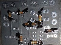
Nice little boards Sangram. Very compact layout.
Could you please upload photo from the backside of the boards.
After studying the forum. I came to one conclusion.
Mr. Pass didn't feed feedback directly to the input stage.
He used one small resistor in series speaker negative terminal. one pot parallels to this sense resistor and connected series to correct negative feedback. That's why he called it as positive feedback amplifier. I am trying to simulating and post the circuit.
After studying the forum. I came to one conclusion.
Mr. Pass didn't feed feedback directly to the input stage.
He used one small resistor in series speaker negative terminal. one pot parallels to this sense resistor and connected series to correct negative feedback. That's why he called it as positive feedback amplifier. I am trying to simulating and post the circuit.
I seem to have lost something in translation.Care to post a diagram and maybe someone can see if you are anywhere near correct.
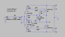
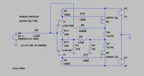
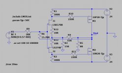
How about this. And what is the damping factor and input impedance?
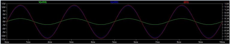
I am getting 19dB gain in LTSpice.
Too much gain,input z about 400k.Circuit is wrong.Read all the F7 posts and you may find a working circuit.
Ha Oreo,
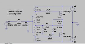
more than 10 times red. Whenever I read my brain goes somewhere. in F7 manual there is no degeneration resistor. But in image green resistor there. What is that green resistor value?. So much highly technical details are there in this thread. actually, I gained some knowledge in a complementary push-pull circuit from Mr. Nelson Pass articles. That credit goes to Mr.Papa. somehow I know voltage feedbacks. Still, I don't know current negative feedback and current positive feedback. Just I am simulating what I have learned.
more than 10 times red. Whenever I read my brain goes somewhere. in F7 manual there is no degeneration resistor. But in image green resistor there. What is that green resistor value?. So much highly technical details are there in this thread. actually, I gained some knowledge in a complementary push-pull circuit from Mr. Nelson Pass articles. That credit goes to Mr.Papa. somehow I know voltage feedbacks. Still, I don't know current negative feedback and current positive feedback. Just I am simulating what I have learned.
^^The circuit above has 2.6/260 = very little positive feedback which is why you see very little difference between NFB and PFB when closing both loops.
If your aim is to create a FW F7, then you can buy one of them, look at the circuit, reverse-engineer it and build your own version.
Or, you could pick up a circuit from here (won't say which one) and enjoy an amplifier that uses both negative and positive feedback and actually build something fun, something that works and who knows - may be pretty close to the production design. Or not, doesn't really matter that much, you can be happy you built an amp with positive feedback.
Hi Sangram,
Actually, the last year I build Aleph 30 and I am happy with that and next 2 years I am not building any amp. My eye caught on F7 because it has the lowest components compared to entire all diyaudio circuits . and no capacitors. I am just simulating. How to calculate input impedance and output impedance?.
Thanks,
Nag.
Actually, the last year I build Aleph 30 and I am happy with that and next 2 years I am not building any amp. My eye caught
on F7 because it has the lowest components compared to entire all diyaudio circuits . and no capacitors. I am just simulating. How to calculate input impedance and output impedance?.Thanks,
Nag.
- Home
- Amplifiers
- Pass Labs
- First Watt F7 review