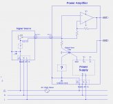
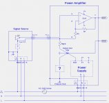
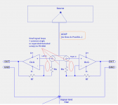
Here is a grounding topology that I have never seen or tried. The idea is to minimize noise currents in the signal ground connection between the signal source and the amplifier by placing a currenting limiting resistor between the amplifier RCA input ground and signal ground, and taking the input ground to the feedback network of the amplifier.
Attachments
Although my original issue was not the GND loop created by the safety earth (as it is solved with the CL60 thermistor),
I would be interested in Mr Pass' opinion about using this resistor between the Signal and Power GND as well.
Specially in F7 as there is a current sensing resistor which is partly Power GND related and partly signal related...
I would be interested in Mr Pass' opinion about using this resistor between the Signal and Power GND as well.
Specially in F7 as there is a current sensing resistor which is partly Power GND related and partly signal related...
F7 output devices
ECX10N20 & ECX10P20 are the suggested output devices, a google search is only bringing up a supplier from the UK:
Purchase Exicon Lateral MOSFETS
Am I missing a US supplier or other source? Any help much appreciated, I have everything else I need for a clone build....or, attempt LOL.
Russellc
ECX10N20 & ECX10P20 are the suggested output devices, a google search is only bringing up a supplier from the UK:
Purchase Exicon Lateral MOSFETS
Am I missing a US supplier or other source? Any help much appreciated, I have everything else I need for a clone build....or, attempt LOL.
Russellc
I have thought more about the that resistor in post #1281 and now think
it is a bad idea. I will but together a simulation to show why. (Hint: noise
across that resistor will appear at the output.)
As I recall, it does every time unless you make that connection directly
on the other channel. If two channels have a common ground then
sometimes connecting one one of the two channels input ground through
a resistor breaks a ground loop.
I don't find that solution very reliable though.
Specially in F7 as there is a current sensing resistor which is partly Power GND
related and partly signal related...
Current sensing resistor on the F7 doesn't affect the grounding -
the signal from that goes back to the + input.
I recall that the central question was about ground currents generated in
the input system when multiple channels share a ground. In the end
this is minimized to the extent that grounds are attached to a "star"
so that they all agree on what ground is.
Other solutions are independent power supplies or monoblocks, and
I forgot to also mention balanced output power amplifiers, like the X
series from Pass Labs, where ground current is negligible.
There was a question about what I meant by measuring voltages
differentially at the output of the simulation, by which I meant across the
speaker terminals.
ECX10N20 & ECX10P20 are the suggested output devices, a google search is only bringing up a supplier from the UK:
Purchase Exicon Lateral MOSFETS
Am I missing a US supplier or other source? Any help much appreciated, I have everything else I need for a clone build....or, attempt LOL.
Russellc
Not that I am aware of. I bought mine from the listed supplier. Fast shipping.
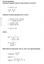
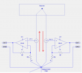
Here is a noise analysis of the circuit shown in post #1281. In the equations shown in the 2nd image, N is the noise voltage across resistor Rgnd, the resistor added between the RCA-In ground and signal ground. OLG is the open loop gain of the amplifier when the feedback resistor Rf is removed. In the resulting equations, CLG is the closed loop gain, defined as CLG = Y/X.
As the equations show, the noise N appears at the output Y. For large open-loop gain (OLG) the equation for the output Y simplifies to:
Y = (Rf+Rs)/Rs * (X-N) + N
As the equations show, the noise N appears at the output Y. For large open-loop gain (OLG) the equation for the output Y simplifies to:
Y = (Rf+Rs)/Rs * (X-N) + N
Attachments
Thanks for your answers Mr Pass!
lhquam: Normally there won't be any big current on this resistor.
But if you look at the simulations as linked above without it the left channel's
output(!) current can be partly flowing via the RCA GND wires and vice versa!
Regarding post #1289: it's tricky: if you draw it this way (and without the source unit)
you could believe that there is an ideal star GND with just 0 ohms from everywhere.
In reality there is a local star GND on the PCBs where the Signal and
Power GNDs are connected together and then they join the Common PSU GND.
With such a layout the speaker GND return current can go easily around the
source via the input GND wires to including the other channel's GND wires.
Last edited:
Assuming that you are referring to the F7 images in the 6Moons review, you are correct about there being local star grounds for each channel. Thus, the F7 wiring departs from the ideal single star ground.
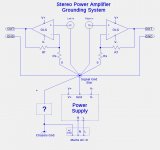
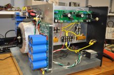
The Pass Labs XA25 is an example of a layout that is nearly perfect w.r.t. grounding. I have built an amplifier similar to the XA25 with a very different packaging scheme and a single star ground, and the amplifier noise levels are well below 50uV RMS. The image on the right shows the star ground.
The Pass Labs XA25 is an example of a layout that is nearly perfect w.r.t. grounding. I have built an amplifier similar to the XA25 with a very different packaging scheme and a single star ground, and the amplifier noise levels are well below 50uV RMS. The image on the right shows the star ground.
Attachments
A star ground is not always optimal.
Look the first image: even if you use a star ground, if you extend
the layout with the source there you see the "parasitic" GND loop.
To solve this check the 2nd image: now the there is no more loop
even if there is a common GND, but this arrangement creates a
pretty big loop for the input wiring as the signal "+" and the GNDs
are running separately from eachother.
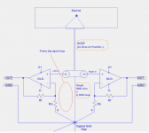
To solve the above 2 check the 3rd image: now there is no GND loop
+ the input wiring can be also donw with a minimal almost 0 loop.
If you don't want to tie the 2 signal GNDs together already at the RCA point,
you can run them separately with a tightly twisted pair of wires to the main GND.
Look the first image: even if you use a star ground, if you extend
the layout with the source there you see the "parasitic" GND loop.
To solve this check the 2nd image: now the there is no more loop
even if there is a common GND, but this arrangement creates a
pretty big loop for the input wiring as the signal "+" and the GNDs
are running separately from eachother.
To solve the above 2 check the 3rd image: now there is no GND loop
+ the input wiring can be also donw with a minimal almost 0 loop.
If you don't want to tie the 2 signal GNDs together already at the RCA point,
you can run them separately with a tightly twisted pair of wires to the main GND.
Attachments
Last edited:
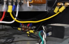
I mostly agree with your conclusion. In the case of my ZD25 amplifier (similar to the XA25), physical packaging constraints required the RCA jacks to be far apart, making the topology of your rightmost diagram impractical. This is the actual topology that I used:
Attachments
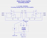
When "tuning" the ground system of the ZD25 I found it reduced the hum by about 10dB by locating the star ground terminal block on the bottom of the front panel, as far as possible from the power supply. This kept the wires from the RCA jacks to the star well away from the transformer and other high current power supply fields.
The Pass Labs XA25 layout is as close to ideal with respect to grounding as anything I have seen. Compliments to Papa.")
The Pass Labs XA25 layout is as close to ideal with respect to grounding as anything I have seen. Compliments to Papa.

Yes, I guess this is exactly due to the still remaining GND loop which could be eliminated as described above....it reduced the hum by about 10dB by locating the star ground terminal block
on the bottom of the front panel, as far as possible from the power supply...
The problem you are fixed upon is just not that significant to me.
Nevertheless, because it is important to you, this morning I took an F7
and put it on the bench and measured the following with my trusty AP.
All noise figures are 20 - 20KHz unweighted. Both channels loaded
with 8 ohms.
With inputs shorted at the connectors, both channels measure 90 uV
of noise, mostly 60 Hz, and about 1/4 of it being 120 Hz.
With the input grounds connected externally by 200 mOhm ground cable
to a preamp, (your sim value, 100 mOhm + 100 mOhm) the noise goes
up to 91 uV, and with a direct short between the input grounds it is 92 uV.
That is about 90 dB below 1 watt, and the extra noise from the two
channel's externally connected grounds is about -110 dB.
If I drive one channel only into 8 ohms at 8 Vrms with the other channel
input grounded and not externally connected ground, I see simple
crosstalk of about 8 mV, and the wave is the same undistorted sine
wave of the driven side. This is about 60 dB down.
When I externally connect the input grounds as previously described,
that figure does up 1 mV, which is a contribution about -80 dB due to
the connection. It is still an undistorted version of the other sine wave.
I simply don't consider these levels of noise and crosstalk to be an issue.
Nevertheless, because it is important to you, this morning I took an F7
and put it on the bench and measured the following with my trusty AP.
There is no other one like you here, Nelson!
Assuming that you are referring to the F7 images in the 6Moons review, you are correct about there being local star grounds for each channel. Thus, the F7 wiring departs from the ideal single star ground.
The Pass Labs XA25 is an example of a layout that is nearly perfect w.r.t. grounding. I have built an amplifier similar to the XA25 with a very different packaging scheme and a single star ground, and the amplifier noise levels are well below 50uV RMS. The image on the right shows the star ground.
Who cares about grounding...I want to see more zd25 pics and a schematic!
- Home
- Amplifiers
- Pass Labs
- First Watt F7 review