Are the simulated issues replicated in reality?Updated simulations: here...
(Still no worries about this GND layout..?)
My last attempt trying to understand... ")
Is there someone who can explain how the FirstWatt amps with a common PSU layout and without
a hum breaking resistor (10R between the Signal GND and the Power GND on the PCB)
are not humming or having major channel crosstalk distortions developed by the giant GND loop formed with this layout?
Is there someone who can explain how the FirstWatt amps with a common PSU layout and without
a hum breaking resistor (10R between the Signal GND and the Power GND on the PCB)
are not humming or having major channel crosstalk distortions developed by the giant GND loop formed with this layout?
My last attempt trying to understand...
Is there someone who can explain how the FirstWatt amps with a common PSU layout and without
a hum breaking resistor (10R between the Signal GND and the Power GND on the PCB)
are not humming or having major channel crosstalk distortions developed by the giant GND loop formed with this layout?
Maybe there isn't a large enough stray field to matter.
I've built balanced gear only, but my experience is with layouts somebody else designed that there can be improvements on grounding scheme and wiring that reduce hum and other noise issues there might be.
Certainly all loops get induced current into the loop if there is changing magnetic field going through, as it seems to be here since the toroid, as the biggest magnetic field generator, is in the chassis and there seems to be a loop. If rca inputs were next to each other and wiring was along with the pcb-psu gound wires the loop area in question would be minimized. Maybe the improvement is large or not, don't know without testing out.
Certainly all loops get induced current into the loop if there is changing magnetic field going through, as it seems to be here since the toroid, as the biggest magnetic field generator, is in the chassis and there seems to be a loop. If rca inputs were next to each other and wiring was along with the pcb-psu gound wires the loop area in question would be minimized. Maybe the improvement is large or not, don't know without testing out.
If such a big size GND loop doesn't matter here I don't know where it matters...
Check it here at this post on the last picture:
An illustrated guide to building an F5
I just noticed there was already a discussion about this grounding layout starting from here:
An illustrated guide to building an F5
So the question still stands: why this GND loop doesn't produce a noticable hum?
And the 2nd one: this loop isn' just a problem source regarding hum, but
as you can see on my spice sims I posted on the other SS topic linked above:
even the output ground current can be flow through the RCA GND causing distortion in the input signal...
Ground loops have an actual closed loop. Assuming that it is not being
induced via multiple AC-outlet grounded chassis, then it would be the
power transformer radiating into the local grounds with the loop closed
by the two grounds going back to the preamp. If you give these grounds
a low impedance connection to each other at the rear of the chassis then
you minimize this.
Further, in testing we rotate the transformer a little bit one way or the
other to minimize the pickup of radiated noise.
Depending on the amplifier, we can get as little as 20 uV noise at the
output terminals.
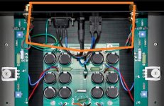
And by that you mean this orange path?If you give these grounds a low impedance connection
to each other at the rear of the chassis then you minimize this.
So even if there is a ground loop, the induced hum is minimal just
because of the distance of this ground loop from the transformer?
And what about the loudspeaker ground current?
As I simulated this layout it turned out that even 1A from the output
current can flow via the RCA interconnect ground wire around the channels.
Isn't this causing some distortion modulating the original signal via the unbalanced connection?
Attachments
There are several kinds of ground loop issues:
- Ground loops within the amplifier itself, particularly between the two channels.
- Ground loops formed by the RCA cable connections to the input source and the AC power chassis ground and its connection to the signal ground of the amplifier.
I don't have a wire at the back as you depict.
Your simulation shows 1 amp of ground current through the RCA's?
Good thing I don't have that wire.....
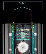
Which wire you don't have? I draw a new image to identify the sections precisely.
If I'm right the Signal and Power GNDs are connected together with 0 ohm on the FirstWatt PCBs: theese are the light green wires.
As there is a common PSU with one, common GND, the 2 channels Signal and Power GNDs are also conencted together with 0 ohm: orange wire.
Assuming a standard preamp, outside of the amplifier the GNDs are also tied together: light-blue wire inside the preamp.
Even if the interconnects look separeted: brown wires.
First issue: a pretty big GND loop is created not so far from a big toroid.
The 2nd thing: even if the hum level is acceptable, a pretty amount of current
can travel via the interconnect GND wire between the wires as shown on simulation: <link here>
and so even the original input signal can be modulated by this GND current.
Or am I missing something in my model..?
Questions:
- If the model is right: why this layout does not cause any major problems regarding sound quality?
- Why don't FW amplifiers use the conventional 10R hum breaking resistors between the Signal and Power GND on the PCB?
- Extra one: the red/blue PS and the green Power GND wires from PSU to Amp PCB aren't twisted together,
leaving a pretty loop, increasing parasitc inductance. Wouldn't it be better to twist them tightly?
Thanks in advance for your anserws Mr. Pass!
Attachments
As you can see on my last image the issue is not related with the chassis and the safety ground at all.In either case, the nominal resistance from signal ground to chassis ground is high enough that the external ground is not a problem.
This GND loop would be formed even without any metal chassis and safety earth conenction.
Half of it is formed by the internal amplifier GND layout having a direct 0 ohm connection as:
Left RCA GND -> Left PCB Signal GND -> Left PCB Power GND -> Common PSU GND -> Right PCB Power GND -> Right PCB Signal GND -> Right RCA GND
Other half at the preamp: the 2 RCA GND is internally connected together of course.
Ground loops have an actual closed loop. Assuming that it is not being
induced via multiple AC-outlet grounded chassis, then it would be the
power transformer radiating into the local grounds with the loop closed
by the two grounds going back to the preamp. If you give these grounds
a low impedance connection to each other at the rear of the chassis then
you minimize this.
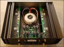
Were the two small wires added from GND to chassis (heatsink) in the J2 (picture from 6moons) to reduce hum?
How does this work in combination with a CL60 between GND and chassis?
Attachments
Here is my favorite amplifier grounding diagram. It shows both the internal star ground scheme and the ground loop path through an external signal source. The boxes shown with a question mark (?) indicate a circuit connecting the signal ground to the AC ground, and some alternatives are shown in the 2nd image taken from RANE publication Grounding and Shielding Audio Devices.
The connection scheme used by the FirstWatt F5, that was not shown in the RANE publication, is shown on the right side of the 1st image.
The connection scheme used by the FirstWatt F5, that was not shown in the RANE publication, is shown on the right side of the 1st image.
Attachments
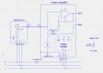
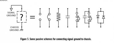
Even if the signal source signal ground has a significant coupling to its AC ground, the power amp is quite insensitive to it when the back-to-back diode circuit is used.
I will try to document some AC ground noise examples with computer soundcard outputs, differential soundcard outputs, and differential soundcard outputs thru an opa1632 differential amp to eliminate to common mode between analog grounds of the signal source and the power amp.
I will try to document some AC ground noise examples with computer soundcard outputs, differential soundcard outputs, and differential soundcard outputs thru an opa1632 differential amp to eliminate to common mode between analog grounds of the signal source and the power amp.
- Home
- Amplifiers
- Pass Labs
- First Watt F7 review