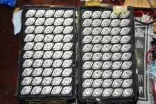
The output fets are ALF08N16V and ALF08P16V lateral MOSFETs from semilab Magnatec. ALFET Lateral MOSFETs.
so , basically , any iteration of oldest and bloody popular Hitachi 2SJ50/2SK135 goodies
Getting to the party late, as usual, I am only up to page 30 of this thread...but based on your comment ZM, am I a lottery winner? I have had these since the late 80's when I was experimenting with MOSFET amps with 6DJ8 cascoded input tubes, cool amps, sounded pretty nice.
Back to reading the next 130 pages..
Cheers
Attachments
Last edited:
That's a really nice stash of old Hitachi lateral Mosfets. I have a smaller set that I've saved from re-building old Hafler DH-200 and DH-220 amplifiers. They are marked with the Hafler numeric codes for Vgs matching.
I still have 2 old DH-200s that need rebuilding and a good cleaning...maybe when I retire in 40 years.

Sure glad I saved these Hitachi FETs, knew they would probably be useful one day. Now to compare the data sheets to the Alfets.
Cheers
PS really looking forward to winter already, so I can start building again. Too much work in the summer to be hovering over a hot iron.
PPS if anyone has other lateral FETs, SITs etc. or 2SJ74BL and wants to trade for some of these...PM me.
Last edited:
The effective input impedance seen by the source, with a 4R load, can be calculated as follows :
For a certain input voltage Vin, ( VLo – Vsen ) = 5.5 x Vin.
Hence Vsen = 0.36 / 4 x 5.5 x Vin = 0.495 x Vin
EUVL, shouldn't Vsen = 0.454 x Vin?
Holes are drilled in the G10 board with a #43 drill bit. Then I prefer to over drill them with a 3/32" drill bit to about a fourth of the way down from the top side. A bit of patience is required to get the drill press stop set correctly. You are then rewarded with a hole that allows easily placing the turret vertically in the board before pressing, without it falling over or going into the hole at an angle while pressing. Still leaves plenty of material for a solid press fit.
Pressing tool is a 1/4" machine bolt with the head cut off, and a 1/8" hole drilled in the end, sized to clear the top of the turret but not the shoulder. Tube depot has the plans. Used in a drill press without the motor running to press the turrets into the board holes. I use a block of wood with a 3 business card thick layer to absorb where the turrets poke slightly through the far side of the board.
Although pressed turrets in a #43 hole are tight enough to use without staking the bottoms, I prefer to stake the turrets with an old center punch reground to a wider angle. You also can grind another 1/4" bolt to do the job. I use a hammer with the punch although you have to be very gentle or the turrets can get bent. Alternatively, I have also used the drill press with the staking tool chucked in it to lightly flare the bottom of the turrets.
This board has a tighter layout than typically recommended. A pressing tool with a tapered end was used to allow the close spacing. Properly sized turret circles with cross hairs were added to the KiCad "user comments layer" of each device footprint and the PCB board layout printed with just that layer as a drilling template. The template was spray glued to the board and removed after drilling. Getting the holes exactly in the center of each of the crosshairs was the challenge!
Brian,
I really like your execution of these old school products, very nicely done. It reminded me that I have a bag of probably 5,000 of these somewhere is my stash of "stuff not yet used but bought because it was a good deal and thought I might need it someday". It looks like a great solution for such a simple circuit.
Thanks for the details and info.
Cheers

Paul:
Thanks for the kind words. I've been up in your part of the Okanagan several times when I lived in the Seattle area. Beautiful country. And sustainable living, unlike what has become of this part of Arizona.
Brian
It is a pretty nice place to live. We have 20 acres outside Vernon with plum and cherry trees, hops too in case I want to brew some beer...
Also have wind and solar power to supplement our grid usage...wood heat as well...a very pleasant lifestyle. Class A fits in very well here in the winter months, some days we don't even need the wood stove when the amps are on...
Cheers
I report some of the findings from the F7 clone alpha test phase here...Some brave guy who built the UDNeSS wants to compare it to the F7.
So we modified the F5X PCB design for him for an alpha build.
Works first time. Very easy to adjust. Very stable thermally, as expected.
Note that :
1. Only thin-film metal-film resistors were used (Dale RN55, RN70, CPF2). No metal oxide.
2. All trim pot are to be replaced by fixed resistors once set up in final case.
PCB size 128x55mm. MOSFET mounting distance 160mm.
No need for long & thin.
Patrick
.
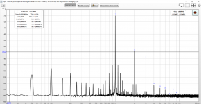
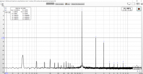
All kinds of measurements and tweaks were performed on basis of what Patrick (EUVL) instructed me to do. The starting point was the F7 clone circuit fed with a regular FW type of CRC power supply with +-22Vdc rails and 1,3 A bias. See the first attachment, with H2=0,13% and H3=0,03% into 8 ohm. The H2 value was 2x higher than what was expected from the LTspice simulation but the ratio between H2/H3 was quite close.
Next we tried what happens if bias current is raised to 1,5A. Well, no effect on H2, only H3 dropped by tiny bit.
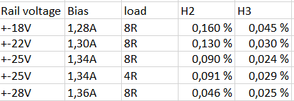
The third iteration round was to see what happens with higher rail voltages. So I fed the amp with my lab supply through the CRC supply with different rail voltages. The results can be seen in the second pic I attached. It was noted that with +-25Vdc rails the distortion lowered quite significantly for both H2 and H3, but with +-28Vdc H2 was further halved while H3 stayed the same. So if you have the sinks and your PSU is up for the task, higher rail voltages can be recommended.
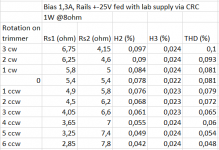
The fourth and the last tweak was to implement a 10 ohm trimmer pot for adjusting the source resistance of the JFETs as described in post #1537 by avdesignguru. So I measured the trimmer beforehand for a few turns to both directions (clock wise and counter clock wise) and the soldered it in and did distortion measurement for each turn of the pot. Results can be seen in the third attachment. The results indicate that the pot had effect only for the second harmonic. This was a cool measurement to carry out as you could see the harmonics change while turning the pot.
The DC offsets were adjusted after each turn of the pot before measuring.In the end the listening test was done with distortion adjusted to H2=0,065% / H3=0,030% with the trimmer and the amp fed with +-22Vdc rails from the CRC supply.
My subjective listening impressions:
At first the F7 clone did not make a huge impression but the more I listened the more I started to like it. Similarly to UDNeSS it is a very pleasant and easy to listen to. Where it shines the most are vocals and soundstage representation. If my memory serves me correctly, I would say vocals and the feel of presence is a little better than with the UDNeSS. Maybe this is due to the tubey-like distortion profile...
Also bass goes deep but my Denon AVR-X3000 is a bit better in controlling the bass with my 4 ohm speakers.
All in all a very good Class A amp once again especially when considering the simplicity of the circuit.
Thanks a lot to Patrick for letting me test this mathematically derived F7 clone version. And obviously huge respect for Mr. Pass for these mind puzzling amps.
Attachments
I report some of the findings from the F7 clone alpha test phase here...
All kinds of measurements and tweaks were performed on basis of what Patrick (EUVL) instructed me to do. The starting point was the F7 clone circuit fed with a regular FW type of CRC power supply with +-22Vdc rails and 1,3 A bias. See the first attachment, with H2=0,13% and H3=0,03% into 8 ohm. The H2 value was 2x higher than what was expected from the LTspice simulation but the ratio between H2/H3 was quite close.
Next we tried what happens if bias current is raised to 1,5A. Well, no effect on H2, only H3 dropped by tiny bit.
The third iteration round was to see what happens with higher rail voltages. So I fed the amp with my lab supply through the CRC supply with different rail voltages. The results can be seen in the second pic I attached. It was noted that with +-25Vdc rails the distortion lowered quite significantly for both H2 and H3, but with +-28Vdc H2 was further halved while H3 stayed the same. So if you have the sinks and your PSU is up for the task, higher rail voltages can be recommended.
The fourth and the last tweak was to implement a 10 ohm trimmer pot for adjusting the source resistance of the JFETs as described in post #1537 by avdesignguru. So I measured the trimmer beforehand for a few turns to both directions (clock wise and counter clock wise) and the soldered it in and did distortion measurement for each turn of the pot. Results can be seen in the third attachment. The results indicate that the pot had effect only for the second harmonic. This was a cool measurement to carry out as you could see the harmonics change while turning the pot.
In the end the listening test was done with distortion adjusted to H2=0,065% / H3=0,030% with the trimmer and the amp fed with +-22Vdc rails from the CRC supply.
My subjective listening impressions:
At first the F7 clone did not make a huge impression but the more I listened the more I started to like it. Similarly to UDNeSS it is a very pleasant and easy to listen to. Where it shines the most are vocals and soundstage representation. If my memory serves me correctly, I would say vocals and the feel of presence is a little better than with the UDNeSS. Maybe this is due to the tubey-like distortion profile...
Also bass goes deep but my Denon AVR-X3000 is a bit better in controlling the bass with my 4 ohm speakers.
All in all a very good Class A amp once again especially when considering the simplicity of the circuit.
Thanks a lot to Patrick for letting me test this mathematically derived F7 clone version. And obviously huge respect for Mr. Pass for these mind puzzling amps.
You have a fairly significant amount of mains harmonics in there. Did you try to narrow down if this is coming from your supplies or your test setup?
...The fourth and the last tweak was to implement a 10 ohm trimmer pot for adjusting the source resistance of the JFETs...
I don't suppose you noted the DC offset at the P3 wiper when you took the measurements.
Hi Patrick, yes, but didn't Morde compensated for the offset by adjusting P1 or P2.
...The DC offsets were adjusted after each turn of the pot before measuring...
- Home
- Amplifiers
- Pass Labs
- First Watt F7 review