I really love to reed this topic about the Firstwatt 7 project and how people try to make a own version. What I was wondering: why does an amplifier with eight resistors, 3 pots and four transistors per channel cost $ 3000?
I understand that running a business, paying staff, advertising, packing the amp to ship, service and warranty also costs money ... but just out of curiosity I would like to know what only the materials cost to this amp ( complete with housing and power supply).
I understand that running a business, paying staff, advertising, packing the amp to ship, service and warranty also costs money ... but just out of curiosity I would like to know what only the materials cost to this amp ( complete with housing and power supply).
There is a lot of R&D that goes into designing and testing any product from Passlabs and Firstwatt. Then there is a lot of hands on labor cost matching and testing all the active parts. Then there is the reliability and standards Passlabs and Firstwatt are noted for to be achieved. I have noticed that Nelson does not even give Diy'ers a design without it being tested and proven before he will release it to us. His reputation is at stake. Even with all the sales every year of his products his companies are really small compared to the big boys. There is a price to pay for excellence. The labor'er is worthy of his pay.
To answer, it might be better to first ask: What do you think an amplifier like this should sell for, and we'll back into a cost, accounting for all the things you mentioned. Bearing in mind we're only making perhaps a hundred units, on-shore, by hand.
And, don't forget development costs (which only get spread out across a hundred units, and don't leave out distribution.")
"if you want to make a million dollars in high-end audio, start with two million."
And, don't forget development costs (which only get spread out across a hundred units, and don't leave out distribution.
"if you want to make a million dollars in high-end audio, start with two million."
Last edited:
Once upon a time this morning, I had some roti prata and iced tea for breakfast. The tea that was only water+steeped strong tea+sugar was RM1.60 and the prata that was only flour+some yeast was RM1.20. Collectively the ingredients doesn't even cost RM0.50 but the breakfast was RM2.80.
So the raw amp component cost about $600,- when you build the amp your self and than you save $2400,- and you have priceless fun to build the amp and then have priceless fun to listen to your own build amp. Thanks for the Answer Zen Mod. I do not think that $3000,- is too much Money also to consider that it made is the US and that you get 3 years of warranty.
I was only curious how much money you are saving
I was only curious how much money you are saving
Member
Joined 2009
Paid Member
you sell for what the market will bear, not a fixed uplift over your costs. That’s why hi end audio is expensive compared with the BOM and why printed circuit board assembly houses have thin profit margins. Having said that, $3k is not expensive for hand made guru-designed limited edition hardware!
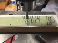
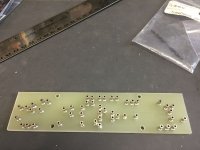
Finally got around to building an F7. Modeled the circuit in LTSpice to make sure it would work. Laid out a schematic and PCB in KiCad and used it to create a drilling template for some old-school G10/turret post boards. I bought some ECX10N20-S and ECX10P20-S lateral mosfets from Profusion in the UK and a matched quad set of LSK170/LSJ74 Jfets from the DIYaudio store. Built the boards to match the mounting layout in a M2x amp I had built.
It all went very well. Bias and DC offset are VERY interactive. Still playing with the Balance pot, trying to use my scope to set it up but thinking there may be a better way. Running about 0.12 volts drop across the 0.1 ohm resistor which yields a conservative 55 degrees C at the transistor body. Amp already sounds very good, very detailed, very different from my F6 as well as very different from my M2x. Well worth the effort so far. I'll try pushing the bias up a bit after I break it in some more. Balance seems to affect the imaging, so I can see that will be critical as well.
Many thanks to Papa for this fascinating PCF amplifier design!
Attachments
So the raw amp component cost about $600,- when you build the amp your self and than you save $2400,- and you have priceless fun to build the amp and then have priceless fun to listen to your own build amp. Thanks for the Answer Zen Mod. I do not think that $3000,- is too much Money also to consider that it made is the US and that you get 3 years of warranty.
I was only curious how much money you are saving
diy audio is not about saving money
Finally got around to building an F7. Modeled the circuit in LTSpice to make sure it would work. Laid out a schematic and PCB in KiCad and used it to create a drilling template for some old-school G10/turret post boards. I bought some ECX10N20-S and ECX10P20-S lateral mosfets from Profusion in the UK and a matched quad set of LSK170/LSJ74 Jfets from the DIYaudio store. Built the boards to match the mounting layout in a M2x amp I had built.
It all went very well. Bias and DC offset are VERY interactive. Still playing with the Balance pot, trying to use my scope to set it up but thinking there may be a better way. Running about 0.12 volts drop across the 0.1 ohm resistor which yields a conservative 55 degrees C at the transistor body. Amp already sounds very good, very detailed, very different from my F6 as well as very different from my M2x. Well worth the effort so far. I'll try pushing the bias up a bit after I break it in some more. Balance seems to affect the imaging, so I can see that will be critical as well.
Many thanks to Papa for this fascinating PCF amplifier design!
What is the "balance pot"?
Well done! Absolutely love your build. Reminds me of my humble diy beginnings only 4 years ago. I started by building two tube headamps and the B1 point-to-point using a similar technique with plexiglass and ferrules.Finally got around to building an F7. Modeled the circuit in LTSpice to make sure it would work. Laid out a schematic and PCB in KiCad and used it to create a drilling template for some old-school G10/turret post boards. I bought some ECX10N20-S and ECX10P20-S lateral mosfets from Profusion in the UK and a matched quad set of LSK170/LSJ74 Jfets from the DIYaudio store. Built the boards to match the mounting layout in a M2x amp I had built.
It all went very well. Bias and DC offset are VERY interactive. Still playing with the Balance pot, trying to use my scope to set it up but thinking there may be a better way. Running about 0.12 volts drop across the 0.1 ohm resistor which yields a conservative 55 degrees C at the transistor body. Amp already sounds very good, very detailed, very different from my F6 as well as very different from my M2x. Well worth the effort so far. I'll try pushing the bias up a bit after I break it in some more. Balance seems to affect the imaging, so I can see that will be critical as well.
Many thanks to Papa for this fascinating PCF amplifier design!
I wish I was
 bright and clever enough to figure out how to build a F7. Of all the Pass amps the F7 is the one I would REALLY love to build (for keeps). I am willing to lay down my soldering iron after that.
 Another F7 imitation breadboard
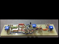
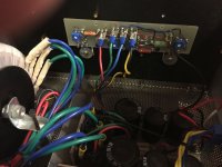
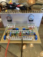
Here is my attempt at a breadboard version - strictly for playing around with values, etc. I used 15-turn pots which makes it easier to dial in bias and offset. The heatsink is only good for about 10 watts or so, but as I said - this is just a test lashup.
I used another old school technique - Tektronix style ceramic-silver strips.
Attachments
- Home
- Amplifiers
- Pass Labs
- First Watt F7 review