It's non-inverting, and the R2 would be the positive feedback resistor. For a gain of five, R5 = 100, and R6 = 25.
Thanks rayma.
Thanks rayma.
See the regular F5 schematic. http://www.diyaudio.com/forums/pass-labs/121228-f5-power-amplifier.html
It is nothing very common with F7 except of insertion of PFB ,
it is basic and approximate principle derived from some very old tube amps types which have extra manual control and extra option for amp operator to gradually adjust and found so called `LS critical DF `point .
it is basic and approximate principle derived from some very old tube amps types which have extra manual control and extra option for amp operator to gradually adjust and found so called `LS critical DF `point .
Attachments

several of them , for English speaking auditory , published in Audio Anthology Vol. 1
..... "When Audio was young"
it seems only Pa is recently keen to pull olde tricks from Rabbit Hat .....


It is nothing very common with F7 except of insertion of PFB ,
it is basic and approximate principle derived from some very old tube amps types which have extra manual control and extra option for amp operator to gradually adjust and found so called `LS critical DF `point .
Thanks for showing that circuit. I was not aware of that trick, and I am still not sure that I understand how it could work. I see that it mixes voltage feedback with current feedback (voltage across the Rsense resistor), but both are negative feedback in that circuit.
It is nothing very common with F7 except of insertion of PFB ,
it is basic and approximate principle derived from some very old tube amps types which have extra manual control and extra option for amp operator to gradually adjust and found so called `LS critical DF `point .
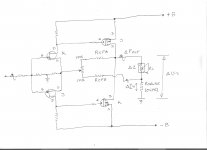
Hello banat. Thank you for your reply. If I remove the resistors of the current feedback path in your schematic, the resultant circuit defaults to diyF5. I do not see positive feedback. Please note that the D and S labels on the upper Mosfet are inadvertently reversed.
Thanks for showing that circuit. I was not aware of that trick, and I am still not sure that I understand how it could work. I see that it mixes voltage feedback with current feedback (voltage across the Rsense resistor), but both are negative feedback in that circuit.
For your better understanding of this CFB-VFB principle here is one related very old article from 1954 .
Attachments
Hello banat. Thank you for your reply. If I remove the resistors of the current feedback path in your schematic, the resultant circuit defaults to diyF5. I do not see positive feedback. Please note that the D and S labels on the upper Mosfet are inadvertently reversed.
By default that CFB loop should be negative feedback to , but in real interaction of delta Z of LS in function of delta F-out that loop it is PFB sometime
") ,
,BTW , yes D and S labels on top output power MosFet are reversed but not intentionally .
Regards !
Hello and thank you lhquam, banat and rayma for your inspiring schematics, and posts.
1. Start with a diyF5 circuit.
2. The input resistors may well be [for example] 1k to the joined JFET gates, and 47K from the JFET gates to ground for a Zi =48 K.
3. Instead of the resistors in point 2, use instead 9.9 K to the joined gates, and a 100 Ohm resistor from the joined gates to ground. New Zi = 10 K. Note that no additional resistors were added to the input of diyF7.
4. Use an adjustable resistor from the power output to the joint gates of the front end JFETs. This is the route of positive feedback to the front end.
5. Positive feedback can only be if diyF7 does not invert the phase of the input signal. Both of the input and the feedback signals to the joined gates are in phase.
6. Thus one feedback resistor was added, two input resistors modified, and positive feedback enabled.
Best regards
For your better understanding of this CFB-VFB principle here is one related very old article from 1954 .
That is probably the most informative post of this thread!
Back to the drawing board (LTSpice).
For your better understanding of this CFB-VFB principle here is one related very old article from 1954 .
Banat
Thank you very much for that fascinating (at least to
Me) paper. Especially interesting where it talked about negative output impedance and also the design featuring variable damping factor control.
In My younger days I built radio receiver circuits featuring a type of positive feedback . They were called regenerative receivers because they sent a controlled amount of the output in phase back to the input such that the signal would be boosted each pass through the circuit. The regen control was turned up until the circuit was almost in oscillation. This was the point where the receiver worked the best. I know that this is vaguely related to the topic , but perhaps of some interest. There is much to be mined for the old circuits for those smart enough . I wish I were .
Last edited:
Banat
...
In My younger days I built radio receiver circuits featuring a type of positive feedback . They were called regenerative receivers because they sent a controlled amount of the output in phase back to the input such that the signal would be boosted each pass through the circuit.
... .
I also built a regenerative receiver in by youth and thought the same when I saw the use of positive feedback in the F7.pdf article.
I also built a regenerative receiver in by youth and thought the same when I saw the use of positive feedback in the F7.pdf article.
I want to give you "Rückkopplung" too.....
that was so nice to look for the right point of "Rückkopplung" and get stations that were very weak!
It is nothing very common with F7 except of insertion of PFB ,
it is basic and approximate principle derived from some very old tube amps types which have extra manual control and extra option for amp operator to gradually adjust and found so called `LS critical DF `point .
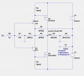
The circuit you show appears to be similar to that in fig. 3 of https://5ad7b68329ae8ddd591c555bf9d.../Loudspeakers_and_negative_impedances-HIk.pdf.
I ran simulations based on that circuit, and found that it would increase damping factor only by floating the power supplies as shown in this schematic. The overall performance based on this circuit looks excellent but it requires one resistor more than the circuit in post #218.
Attachments
- Home
- Amplifiers
- Pass Labs
- First Watt F7 review