Thanks ZM.well...... if it works for you .....
did you tried what I prescribed ?
Yes, first try was shorting the input, still had a hum. Then with clippy leads grounded the tab on the XLR body, that made the biggest single improvement. Then separated the power supply grounds from the FE board grounds and with clippy leads tried every option of terminating (including markup in pic). Connecting both the PS and the FE board directly to one side of one cl60 (with the connection point of the ground wire to the center between PS, should have made a better drawing) was the lowest amount of hum, almost good enough, had to literally put your ear to the driver to hear it. Then for fun, since I don’t know any better, added the second cl60 just for the FE board.
let us know how it sounds
while on bench , you can check Aleph AC gain
for that - run any Freq you know that your AC DVM can cope with (400-500Hz) , level - some round value on output - volt or so ; then simply measure AC voltage across source resistor of any lower positioned mosfet, write down; then measure AC voltage across source resistor of upper mosfet , write down.
then write here
")

Thanks ZM for all your advice. Amps sound great! Listening right now.
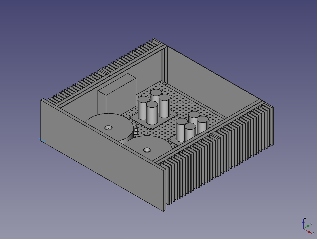
Here is a pic of the final ground wiring, no hum at all.

Been bust with car stuff, but took some time today to follow your instructions to test Aleph AC gain.
Since I don’t really know what I’m doing, or if I did it correct, here is a list of the steps I took.
I connected the “Function Generator” to the amp with a couple adapters to XLR, settings to Sine Wave, 500 Hz, and adjusted the units “amp” setting to 1VAC output, measured both settings with my Fluke and confirmed at XLR input-jack of amp.
Then connected the adjustable “load” that I built and selected 8 Ohm.

Turned on the amp, and started hooking up the clippy leads from the Fluke to the source resistors. Then panicked because I smelled something burning, but was only the “load” resistors.
So I measured across all the (+) side and (-) side source resistors. All read 0.001 VAC.
Does this seem right?
Thanks.
that seems right , for , let's call it , 50% of Aleph AC gain
meaning - Aleph CCS is contributing 50% of output swing
so , you're good
Thanks ZM!
So the build went pretty good, only burned up one capacitor, they sound terrific, and now you confirm that the gain is where it’s supposed to be.
Any other tests I should make? Am I good to just keep listening and enjoying?
I have my Mercedes project stripped and at the paint shop and my FFR 818 transmission pulled and at the trans shop (tore it up my last outing at the local SCCA event last year) so I guess I have a couple weeks to work on my F5 rebuild. Although I have a lot of Mercedes chrome to polish!
well , put some muzak through them , while polishing
(let's pretend that hand polishing is in case , not standing by loud polishing wheel
Thanks ZM. Unfortunately my garage it too far away from the living room to listed to the system.
But I still take time to listen to the music!
As I’m finishing up this system, and getting the cabling sorted, how do I figure out what the input impedance of these amps are? How do you measure?
I guess rule of thumb is solid state is usually low and tube is usually high. I’m using a tubed based DAC and a tube based Pre so I think some improvements can be made to correct the imbalance with the cables.
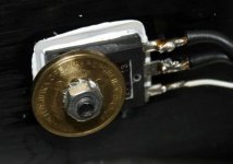
sort of game/joke , although absolutely functional
even if some are saying that using coins in destructive way is criminal act ....... I'm having difficulties to see it as destructive
I won't tell Vucic...
sort of game/joke , although absolutely functional
even if some are saying that using coins in destructive way is criminal act ....... I'm having difficulties to see it as destructive
Just use coins from another country ;-)
These amps are SPECIAL!!!
My Mercedes project is still at the paint shop this weekend. I did some polishing on the grill and bumpers, but not as much fun when I can’t put them right on the car.
So stopped and played with stereo stuff, more fun.
Brought out my Ekta Grande speakers and Transparent “Super” cables to give a listen, now that they are broken in and running great. The built in JBL LE8T’s sound pretty good. But missing the deeper base and highs of a good 3-way.
I am super excited on how these amps sound. I would say a pretty big jump up from the F5 turbo v3’s that I stole the power supplies from.
I’m not sure how much the extra voltage and capacitance weights in, but the punch and power is amazing.
Anyway, thanks Zen Mod for your design, boards, time, and hand holding!
Thanks, Zen Mod for this outstanding design and very informative thread. I believe in a single transistor doing all the work at the output, albeit the price you pay when it comes to the total power dissipation, no coupling caps in a signal path, and thick copper traces where it counts on a PCB. The trace thing doesn't bother me really that much because I double up everything with pure copper or silver ribbons anyway
I am planning to make one of these for my 4 ohms-flat Dynaudios, that I was able to drive nicely even with a 3W single-ended valve amps...
I am planning to make one of these for my 4 ohms-flat Dynaudios, that I was able to drive nicely even with a 3W single-ended valve amps...
Last edited:
- Home
- Amplifiers
- Pass Labs
- About possible Babelfish J interest