ZM, I’m grateful for the help.aha
yup , problem often is my multitasking
in fact , I am the problem , due to multitasking
just confirm - you're having 0R47 resistor mounted now ?
Welllll, very good question. Yesterday morning I would have answered yes. But after spending some time measuring and pre-checking everything in the afternoon, I noticed I had bought, and stupidly installed, 0R.47 resistors.
So the correct ones are on the way.
No short answer, in a couple days I will have 0R47’s mounted.
In a couple of days I will be installing the correct 0R47 5w resistors.well , now I'm confused .....
is that a typo , for my eyes (what you wrote ) 0R.47 is pretty close to 0R47 (means 470m)
what you really meant to type ?
")
Would the Babelfish J be happy with 18 V rails? I need a summer amp and a mini Aleph J was the plan but the Babelfish has cascodes and that seems interesting. No rush on this as I do have a backlog of projects but I am retiring the end of this summer and expect to find time to clear up that backlog over the next year.
Sorry was sleeping. Right now my mistake is sitting there reminding me to double check before soldering!
0R.47’s 5w are soldered in.
why changing them , if they're good ?
Would the Babelfish J be happy with 18 V rails? I need a summer amp and a mini Aleph J was the plan but the Babelfish has cascodes and that seems interesting. No rush on this as I do have a backlog of projects but I am retiring the end of this summer and expect to find time to clear up that backlog over the next year.
it'll work as charm
ZM, I guess I picked the wrong week to stop sniffing glue (movie reference)!!
I don’t know what I was thinking yesterday. I have the correct 0R47 resistors soldered in.
Below is a marked up schematic of what is soldered in now. Can you take a look and let me know what needs changed? Looks like I’ve taken some values from two different schematics.

I don’t know what I was thinking yesterday. I have the correct 0R47 resistors soldered in.
Below is a marked up schematic of what is soldered in now. Can you take a look and let me know what needs changed? Looks like I’ve taken some values from two different schematics.

Dear ZM,
mmh, all my programs say the cdr file ist defective (on my Mac). Can you provide it me again and / or if possible as hpgl, thanks!
Enlarge thumbnail. Press right button on mouse and drop down menu opens: 'save to desktop' from drop down menu. Saves on my iMac {OS 10.11.6} as a .jpg
ZM:
That is one hell of a good logo!
Last edited:

here it is , finally ;
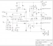
look at attached schm , I believe I edited everything ;
note - input JFets doubled , doubled current through them (LTP) , BD140 cascodes instead of eeenyweeeny BC critters
few resistors marked as 1W - you can easily buy metal oxide ones , tiny as regular 600mW metal-films ; up them smidge above pcb
for more necessary info about general approach (how to connect Daughter boards , recipe for eternal life and no need for Viagra ....) read these posts:
#21 (important Snake Oil notes)
#80 (how to actually do it ; imagine 2 daughter boards per side , paralleled)
Greedy Boy Coasttocoast asked for something with 38Vac rails ........ that would be aroundish 47-48Vdc
same applicable
Boyz - you're nutz ........ who need that sort of power ?

I’m not sure how I got sideways/confused, so best to go back to the beginning.
I received the balance of resistors I needed and swapped everything to exactly match this originally provided schematic to match my original power supply.
Been really giving my Hakko 808 some good use!
Here is a pic of the completed board. In wanting to stay with all PRP resistors I had to get a little creative with the 3ea 1W ones.

Going to put some power to it later today when I get back home and see what happens!
give me few hours and I'll post schematic I promised (or triple check already posted , whatever)
got sidetracked these days ......... you know - that thing Muggles calling real life
Oh great! Thanks for taking the time to help me.
Lazy ZM
see enclosed (repeated) schematic
looking at it , I can see that I didn't made (miracle!) any serious mistake ...... but looking at pic of your pcb , I see that YOU made few ....
most important thing(s):
-source resistors for 6 pairs of outoput mosfets , as I marked them , are 1R ..... and you change them to 0R47 ; OK with me ......
-now , BIG BUT! : according to source resistors of 1R , 6 of them in each half , demands that in SENSE group ( resistors in series with output) we have 6pcs of 0R47 , or 12pcs of 1R ........ practically half value of all source resistors (in one half) paralleled ........ and that is your mistake , as far I can see from pics..... you have too few of 0R47s in SENSE group
-Conclusion - if you have 6 mosfet vertical pairs ,each mosfet having 0R47 source resistor , in SENSE group you need to have either 12 paralleled 0R47 , or 6 paralleled 0R22
had few mishaps with values of trimpot and resistor in input JFet drain , corrected , red marked
rest is OK
Attachments

Lazy ZM
see enclosed (repeated) schematic
looking at it , I can see that I didn't made (miracle!) any serious mistake ...... but looking at pic of your pcb , I see that YOU made few ....
most important thing(s):
-source resistors for 6 pairs of outoput mosfets , as I marked them , are 1R ..... and you change them to 0R47 ; OK with me ......
-now , BIG BUT! : according to source resistors of 1R , 6 of them in each half , demands that in SENSE group ( resistors in series with output) we have 6pcs of 0R47 , or 12pcs of 1R ........ practically half value of all source resistors (in one half) paralleled ........ and that is your mistake , as far I can see from pics..... you have too few of 0R47s in SENSE group
-Conclusion - if you have 6 mosfet vertical pairs ,each mosfet having 0R47 source resistor , in SENSE group you need to have either 12 paralleled 0R47 , or 6 paralleled 0R22
had few mishaps with values of trimpot and resistor in input JFet drain , corrected , red marked
rest is OK
Fantastic! We are getting close. Thanks for looking this over and being patient with me.
Please indulge me a couple more questions.
So I need to swap out TP1, 20 Ohm trimpot with a 200 Ohm trimpot, and change R7 to 390 Ohm.
On the daughter boards I have 1 Ohm/3W resistors and a 180 Ohm resistors for each mosfet.
On the front end board I have OR47’s for positions R31-R36. So I need to swap these out for 1 Ohm?
Thanks
TP1 was marked as 500R , now going to 200 ..... though - you can leave 500 in , just having less turns to fiddle with
having 1R on daughterboards (that's my bad , I understood that you have them ALL 0R47) , leave those 0R47s on main board and do not touch source & sense resistors at all
remember ........ as I wrote in previous post - if you have 6 of 1R under mosfets , you need half of that in SENSE group ....... and that's exactly 6 paralleled 0R47s
so , to repeat - now I have necessary info that I can say that source and sense resistors are good
- Home
- Amplifiers
- Pass Labs
- About possible Babelfish J interest