huh
few busy days , besides having head/eye troubles , due to some funny virus (that's fun , having kidoe in elementary school)
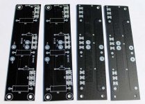
I sorta postponed/delayed fabrication of pcbs (do not worry , un-paused today ) due to repeated demands of making them adaptive to usage of multiplied outputs , based on two additional triplet mosfets daughter-boards per channel .
so , it's done , along with minor changes to minimize any possible PSU rippling influence (due to increased current demands with more outputs) , safe dissipation of funny (led string feeding) ccs , logical rails routing to daughter pcbs , logical sense routing etc. blahblah
so - for full stereo blastbanghurah , you need two base pcbs and four daughter boards
also tried to adapt them as possible to armchair DIY Club , to accommodate as close as possible universal-mounting-specification-v2.1 (which is far from Wild West Miracle Elixir )** .......
**anyway - if you are in this hobby/passion/whatever - you need to have few drills and taps around , and you need to know how to use them ...... nobody can't predict all possible drill/mounting schemes in this world ...
few random notes :
output mosfets of choice are IRFP150 - each one worth of two PapaIRFP240usuals ; if you're good with up to 30V rails-2A Iq - 50W/mosfet dissipation (whichever you meet first and/or together) - use one pair on basic pcb
if you need more coyones , skip basic pcb mosfets , put daughter boards and :
- for more W @ 4R load - increase sum Iq , leave rails at basic level
- for more W @ 8R load - increase sum Iq , up rails to ...... well , that you either need to know , or need to ask
for both cases - best to ask for advice - is there something needed to change , regarding few values on base pcb and how to make proper wiring
so - base pcb iteration - worth of two pairs of PapaIRFP240usuals
- base pcb sans onboard mosfets + two daughter boards - worth 6 pairs of PapaIRFP240usuals
all that speaking of one channel
in any case - minimal Iq per mosfet vertical is aroundish 400mA ; maximal - better look in conjuction with rails value , no more than 50W/device .... so veeeery close asymptotic to real FAB area
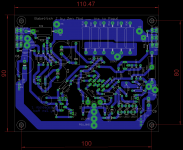
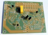
base pcb is one side copper, with tricks
daughter board two side copper , same tricks
now , on to some relaxing ...... there is sun out and I need some air through my ears/nostrils/eyes/two cells
few busy days , besides having head/eye troubles , due to some funny virus (that's fun , having kidoe in elementary school)
I sorta postponed/delayed fabrication of pcbs (do not worry , un-paused today ) due to repeated demands of making them adaptive to usage of multiplied outputs , based on two additional triplet mosfets daughter-boards per channel .
so , it's done , along with minor changes to minimize any possible PSU rippling influence (due to increased current demands with more outputs) , safe dissipation of funny (led string feeding) ccs , logical rails routing to daughter pcbs , logical sense routing etc. blahblah
so - for full stereo blastbanghurah , you need two base pcbs and four daughter boards
also tried to adapt them as possible to armchair DIY Club
, to accommodate as close as possible universal-mounting-specification-v2.1 (which is far from Wild West Miracle Elixir )** ....... **anyway - if you are in this hobby/passion/whatever - you need to have few drills and taps around , and you need to know how to use them ...... nobody can't predict all possible drill/mounting schemes in this world ...
few random notes :
output mosfets of choice are IRFP150 - each one worth of two PapaIRFP240usuals ; if you're good with up to 30V rails-2A Iq - 50W/mosfet dissipation (whichever you meet first and/or together) - use one pair on basic pcb
if you need more coyones , skip basic pcb mosfets , put daughter boards and :
- for more W @ 4R load - increase sum Iq , leave rails at basic level
- for more W @ 8R load - increase sum Iq , up rails to ...... well , that you either need to know , or need to ask
for both cases - best to ask for advice - is there something needed to change , regarding few values on base pcb and how to make proper wiring
so - base pcb iteration - worth of two pairs of PapaIRFP240usuals
- base pcb sans onboard mosfets + two daughter boards - worth 6 pairs of PapaIRFP240usuals
all that speaking of one channel
in any case - minimal Iq per mosfet vertical is aroundish 400mA ; maximal - better look in conjuction with rails value , no more than 50W/device .... so veeeery close asymptotic to real FAB area
base pcb is one side copper, with tricks
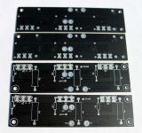
daughter board two side copper , same tricks
now , on to some relaxing ...... there is sun out and I need some air through my ears/nostrils/eyes/two cells
Attachments


Last edited:
 Have fun in the sun ZM, my semi-annual golf outting is this afternoon in beautiful weather.
From what I read above, the IRFP150 x 2 on the base board will be the equivalent of the 2 "papa-standard" pairs on my Aleph J from the DIYAudio store. I hope to do the new one as mono-blocks, and keep the best sounding amplifier, giving the other to my son.
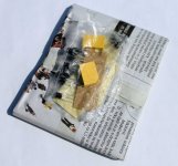
group shipment made today ..... 
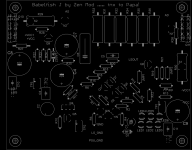
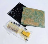
that means that I'm going to do someting about few informative pics and schematics and sketches
all that , as always , from my own Futile Attempts Method Lab , which is (btw.) situated right near to OPLDF
few pics , read captions ...... lazy to do that tiresome insert into post thingy
that means that I'm going to do someting about few informative pics and schematics and sketches
all that , as always , from my own Futile Attempts Method Lab
, which is (btw.) situated right near to OPLDFfew pics , read captions ...... lazy to do that tiresome insert into post thingy
Attachments
-
 06-Daughter boards.jpg75.2 KB · Views: 282
 -
 07-you'll get that twice.jpg94.5 KB · Views: 382
 -
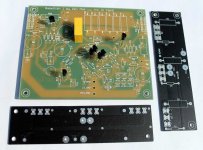 08-or you'll get that twice.jpg99.9 KB · Views: 400
 -
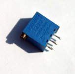
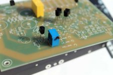 09-use this trimpot shape in all positions.jpg44.1 KB · Views: 372
 -
 05-Daughter boards.jpg112.1 KB · Views: 341
 -
 04-Daughter boards.jpg92.8 KB · Views: 347
 -
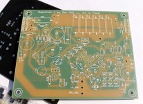
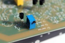
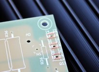
 03-what you get basic-JFet CCS detail.jpg83.5 KB · Views: 360
 -
 03-anemic green.jpg90.2 KB · Views: 402
 -
 02-what you get basic.jpg83.7 KB · Views: 454
 -
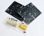 01-what you get basic.jpg72.4 KB · Views: 463
few more pics
btw - side-screw trimpots either pins in line or zig-zag , it'll fit
if pcb mounted vertically , all trimpot screws will point upwards , with clear path to them
btw - side-screw trimpots either pins in line or zig-zag , it'll fit
if pcb mounted vertically , all trimpot screws will point upwards , with clear path to them
Attachments
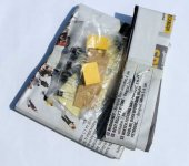
About those 1uf mkc phillips
There are blue and yellow body with same code number
What is the different??
Thx.
nothing - just color
( I can make them in any color you wish .........
)Beautiful work friend. Professional !
Buenisimo macho....
tnx .
as everything from Futile Attempts Method Lab
Mine has shipped, thanks ZM!
Any special recommendations on soldering the power mosfets to the backside of the board, as the holes are not through plated? I'm used to bolting the mosfet down, fit the legs to the holes, and then boring the board down, and soldering the mosfet legs in.
My thought is the the mosfet has to be mounted on the board, an the board then bolted on. Then the holes for the mosfet bolts can be located, drilled and tapped.
Excuse my noobiness, but if there is an easier way, please enlighten.
Also, will the 4u modushop chassis do? I used the 5u one from the DIYShop for my current Aleph J.
Thanks again,
Michael
as I said , I'll put few more pics and few words these days .......
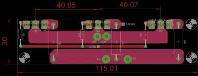
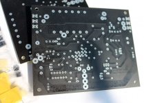
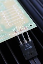
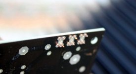
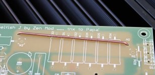
as you can see from pics - there are some small funny holes/pads around each mosfet leg pad ....... trick borrowed from Japanese amps of yore - one wire bridge at both sides of each mosfet pin
that way you can put mosfets through hole either from bottom or top side , solder it either from top or bottom side , or you can put pins/legs laying on top and solder them to wire bridges
hey - you can put pins/legs laying on bottom side and solder them to pads , while wire bridges are taking care of pads not peeling off
there was no need for two layer board ....... and I got that idea simply because I did repair one damn huge Pioneer drek amp in these days ......
Last edited:

sorry , forgot to reply to 4U question - you can use it , with some caution , applying Papa's palm rule - crikey hot
most probably counting on slightly smaller dissipation ...... or simply make Babysitter
....... for all amps
most probably counting on slightly smaller dissipation ...... or simply make Babysitter
....... for all amps
Attachments

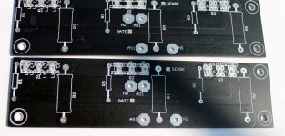
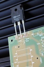
......... trick borrowed from Japanese amps of yore - one wire bridge at both sides of each mosfet pin...
so , with addendum of some niceandshiny solid core wire , you can mount output critters on base pcbs in three way , bending legs accordingly and soldering them on side where it's easiest; same applies to daughter pcbs , where small wire bridges are also implemented (pics in #26)
Attachments
Last edited:
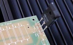
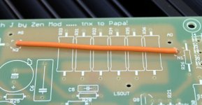
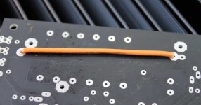
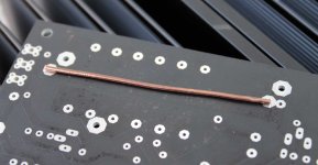
regarding pcbs in current realm ... just for fun of it there is place for one fat or even fatter wire bridge , connecting upper and lower mosfet (group)
-place nice one on either side of pcb on N1-N2 pads or
-in case of not using daughter pcbs place fat one on either side of pcb on AD-AS (all drains-all sources) pads or
-place fat one on pcb bottom on N1-N2 pads ; that's universal solution , covering both cases - just base pcb mosfets or daugther pcb mosfets
Attachments
- Home
- Amplifiers
- Pass Labs
- About possible Babelfish J interest