The Mains input is feeding an interference field into your amplifier casing.
The transformer then passes the Mains and it's interference to whatever is downstream.
Any LOOP in the wiring from the Mains to your amplifier will work as an aerial.
All these loops will transfer interference. All it takes if for the current to change, DC non varying current does not create interference.
You must minimise the LOOP AREA of every wire pair that comes from the Mains to your amplifier. The Flow is the Live wire, the Return is the Neutral wire.
The mains to the fuse. The mains from the fuse to the transformer. The LV from the transformer to the rectifier. The LV from the rectifier to the mains smoothing bank. The LV from the main smoothing bank to the amplifier. Some of these LV wires will be triplets instead of pairs.
Then you have the signal input cabling. This too can have LOOP AREA. You must minimise the loop areas of every signal wire pair. The left channel Flow and Return to the amplifier, the right channel flow and return to the amplifier.
The left speaker flow and return from amp to output terminals. the right speaker flow and return from amp to output terminals.
I count 9 pairs, but you may have more. Sort out the pairs.
Then come back.
Looking at the original F5, (I have clones of the pcb) I see that + and - are drilled.
The main difference between Orig F% and my bad clone: Transformer is in comparison very near to input...
And, Andrew, of course my + and - are not drilled. I'll come back with results on wednesday.
The main difference between Orig F% and my bad clone: Transformer is in comparison very near to input...
And, Andrew, of course my + and - are not drilled. I'll come back with results on wednesday.
Next...
So. I twisted the wires (see pics.)
Result: Maybe a bit less hum. But far worse than lab supply.
I also tried to shortcut the input on pcb with a screwdriver: No effect.
A friend listened to my setup: His opinion is, the hum sounds very hard, like some rectifier spikes... Could be? My transformer and rectification is very nearby input....
Next days I will listen to it on my normal speakers. They are less sensitive that my papercone tryouts...
Attachments
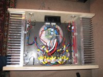
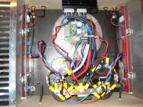
The transformer is huge. About 3x as big as necessary. It has a similarly large magnetic field. That field may be causing the hum.
The bridges are located in a perfect place to be collecting some of the hum, as are many of the wires sitting on top of the transformer.
Every time I have an issue like you describe, changing the orientation of the Toroid will fix it.
An easy experiment - un-bolt the transformer and rotate the Z axis 90deg towards the front (or rear, whichever direction is easier using your wires), so the transformer is sitting on it's edge. I strongly suspect that the Hum will change, it may get stronger, it will probably weaken, but either way you will see that the transformer is doing something.
With both channels. But switched off, feeding as is with a lab supply, it's dead silent.
Yes, but now you have two things changed :
- your wiring (routed diffrently and only DC)
- other power suppy (so maybe less ripple voltage)
If no change, then start the mechanical work as suggested by the others.
Regards,
Nick
- Status
- This old topic is closed. If you want to reopen this topic, contact a moderator using the "Report Post" button.
- Home
- Amplifiers
- Pass Labs
- Firstwatt F5, some Problems...