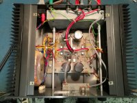
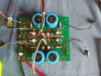
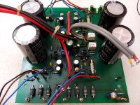
Shame it was not last week because I was at home (you know "Covid" crap) but going back to work tomorrow.
I noticed earlier that my transformer is lose and moving on the mounting plate will take care of that and measure the voltage across those diodes tomorrow after work.
Will also have a look at replacing the germanium driver transistors pair.
That picture looks exactly like mine but my board is green
I noticed earlier that my transformer is lose and moving on the mounting plate will take care of that and measure the voltage across those diodes tomorrow after work.
Will also have a look at replacing the germanium driver transistors pair.
That picture looks exactly like mine but my board is green
Last edited:
Hi,
waiting to receive the ordered components, I measured the voltage at the ends of the zener series and, as expected, it is about 32V.
The thing is very strange. On your KL there is however a strange parallel with two zener one of 6V and one of 12V with a measurement of about 5.5V on the parallel. At this point the 12V zener could be removed, unless it was inserted to increase the final wattage.
On my KL the series of the two Zener from a voltage of 31.7V (12V + 20V) as I assumed.
One of the two KLs or both of them have the wrong zener values and/or montage.
Do your KL's zener look original? or do you notice that the welds have been redone?
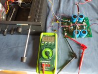

Something is wrong with that amplifier...
The power supply is around 24Vdc (24/0/24) from a 18/0/18 transformer so how can you have 31V at the Zener ?
Or am I missing something ?
My amplifier was untouched until 2 of the rectifiers failed so the zener are original.
The power supply is around 24Vdc (24/0/24) from a 18/0/18 transformer so how can you have 31V at the Zener ?
Or am I missing something ?
My amplifier was untouched until 2 of the rectifiers failed so the zener are original.
Last edited:
... I'm a little less worried about the zener issue.
I have obtained the part of the circuit, of which it is part, and it seems to be the one that drives the two relays which are excited with delay to avoid annoying bump in the speakers.
Anyway I will try with zener with lower voltages to see if it works anyway ...
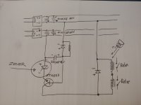
I have obtained the part of the circuit, of which it is part, and it seems to be the one that drives the two relays which are excited with delay to avoid annoying bump in the speakers.
Anyway I will try with zener with lower voltages to see if it works anyway ...

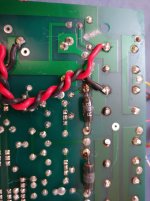
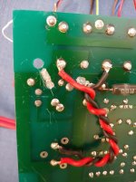
That is very strange cutting tracks to connect then again with wire ?
Mine doesn't have that and like I mentioned it only had 1 failure on the main rectifiers.
Another thing the big resistors on the back of the board are R27 or 2,7 Ohms yours are R68.
Output devices are BZV64/65 how about yours ?
Mine doesn't have that and like I mentioned it only had 1 failure on the main rectifiers.
Another thing the big resistors on the back of the board are R27 or 2,7 Ohms yours are R68.
Output devices are BZV64/65 how about yours ?
Hi,
the work continues.
I discovered the mystery of the zener diodes.
The two 18V relays they must drive are faulty.
I took them apart and tested them with my 0-26V power supply and they don't excite even at 26V. This is the reason why, who has previously worked on this amplifier, has increased the zener voltage to 32 V (series of 20 + 12). Furthermore, one of the two does not close the contact to ground well and therefore the signal, between the preamp and the final stage, is connected even before the relay is excited.
I replaced the two relays with a 24V "Finder" model, currently driven by the 20V zener.
The background noise has decreased a lot but is still slightly present. The next step will be to try to replace the four germanium transistors.
In this amplifier the two trimmers present are used to adjust the offset voltage on the output terminals and not the bias current at rest.
The bias current, measured with the voltmeter on the 0.68 ohm output resistors, is about 370 mA (250mV / 0.68ohm). It seems a bit high but I don't know how to adjust it. It could also be normal for an A class.
I also replaced the output terminals with larger ones ...
I have another curiosity to ask you: On my KL the balance control does not decrease until you no longer hear a channel, but the volume decreases only slightly. Is this the same on your Kelvin?
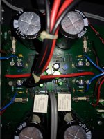
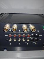


I will try to insert the BC337 and BC 327, they are quite similar to the mounted ones, with germanium. In reality only the Veb on the "germanium" is 10V while on the "BC" it is 5V.
I will try to understand if something needs to be changed, but without a scheme it is difficult.
I will try to understand if something needs to be changed, but without a scheme it is difficult.
Updates, at work.
I replaced the germanium transistors with the BC327 / BC337 silicon pair.
I tried it for a short time, but it sounds very good, really good. Full and rich with Linn Tukan speakers, imposing!
The hum is almost completely gone and is independent of the volume level. It is inaudible unless you put your ear close to the woofer, but even in this case it is very tractable and I think it is physiological for this type of circuit.
In the next few days I will extend the listening sessions and the last step will be to bypass the balance control.
Now I have replaced all electrolytics including main filter caps, rectifier diodes and some polypropylenes and I added even inrush current limiter for soft start. Amp works perfectly. Heatsinks are at 45 degree Celsius. I got some DC-offset at outputs, 69mV on right channel ja 19mV on left, is that acceptable???
- Home
- Amplifiers
- Pass Labs
- Help with Kelvin Labs Integrated
