Have been working on this for a while, but here it is - a headphone amplifier based on the F5. In this case, with a few twists:
Designed for (Stax) electrostatic headphones, and will swing +/-250V at the output
Symmetric construction, inspired (but probably not as elegant) as the X5 from EUVL
No thermal compensation, but simple servos
The boards have voltage regulators on there as well
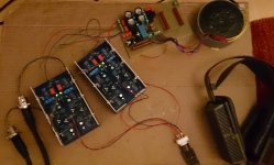
This picture shows the testrun I did tonight - I just had to try it, once it was up and running (and not smoking ) (well, almost no smoke )
The two boards with heatsinks are the amplifiers, the other board is the power supply for the amps and bias, powered by a custom toroid.
Hope you like it, more details later....
Designed for (Stax) electrostatic headphones, and will swing +/-250V at the output
Symmetric construction, inspired (but probably not as elegant) as the X5 from EUVL
No thermal compensation, but simple servos
The boards have voltage regulators on there as well
This picture shows the testrun I did tonight - I just had to try it, once it was up and running (and not smoking
) (well, almost no smoke )The two boards with heatsinks are the amplifiers, the other board is the power supply for the amps and bias, powered by a custom toroid.
Hope you like it, more details later....
Attachments
I hope you will forgive me.
Could not resist the challenge.
Let's see how close I get ..........
PS
I don't think you are using 600V P-FETs.
I can only find them in TO247 from IXYS.
But I guess you are using Fairchild, so rails limited to +/-250V ??
Patrick
.
Could not resist the challenge.
Let's see how close I get ..........
PS
I don't think you are using 600V P-FETs.
I can only find them in TO247 from IXYS.
But I guess you are using Fairchild, so rails limited to +/-250V ??
Patrick
.
Attachments
Last edited:
Actually if one is outputting +/-250V differential, one might even get away with +/-130V rails.
Then plenty more choices for FETs.
The lower rail voltages also make life easier for the cascode FETs.
One can then use the smaller Zetex ones, such as ZVN4424 / ZVP4424.
The one I post above will do +/-400V differential and still have decent performance.
Only simulation of course.
Patrick
Then plenty more choices for FETs.
The lower rail voltages also make life easier for the cascode FETs.
One can then use the smaller Zetex ones, such as ZVN4424 / ZVP4424.
The one I post above will do +/-400V differential and still have decent performance.
Only simulation of course.
Patrick
Hi Patrick, I was hoping you would show up
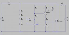
Here is the amplifier schematic. It will simulate, but the results will not be real, reason being that I couldnt find the original sim on my hard drive and so I did not include the models for the output MOSFETs. But if you plug them in, it should work.
I used the combo of PF5102 / 2xJ270 since they have comparable gm and capacitances, same for the FQP3P50/FQP5N50NZ. Well, the match is not superb, but at least for the output devices, due to the heavy source degeneration, it doesnt matter that much. Certainly the circuit can be optimized, but it does work pretty well!
This also doesnt have the servos and power supplies, this will come in a later post....
enjoy!
Attachments
Forgot to mention - R13/R14 as well as R30/R31 are trimpots, so I can play with the source degen of the input stage. And the base voltages of the cascode bipolars are also adjustable so I can finetune the DC offset on the output (this explains the 4 trimpots you can see on the picture of the PCB).
As it stands, it does have a couple volts DC at the output, which is completely ignored by the headphone. Eventually I will finetune and get it to zero.....
As it stands, it does have a couple volts DC at the output, which is completely ignored by the headphone. Eventually I will finetune and get it to zero.....
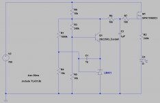
Here is the regulated bias for the headphone. Stax "Pro" types require 580V, standard types 230V (I believe), and there are various other models on the market. R2/R3 are in fact a 10k trimpot to adjust the bias voltage from 200V to 600V. It is powered by a 600V/10mA winding on that custom toroid transformer, followed by a rectifier (1N4007 works fine here) and a cap (1uF or so).
It is using the good old '431 in a rather unusual configuration, so I had to invert the output to be able to use a n-channel MOSFET. You may want to use a 800V power MOSFET in this configuration, I just had no other simulation model.... But in principle it works fine. In fact, on my board I used a 1200V IGBT - had to increase R9 to 10k since the threshold voltage of that device is much higher.
The headphone bias pin is connected to the drain of the power mosfet, through a 1M resistor, followed by a 1nF cap, and another 1M resistor.
enjoy
Attachments
Last edited:
Very nice, and very close!! With regulated 250V rails, I can use 2SC3503/2SA1381 as cascode transistors with sufficient margin.
I hope you will forgive me.
Could not resist the challenge.
Let's see how close I get ..........
PS
I don't think you are using 600V P-FETs.
I can only find them in TO247 from IXYS.
But I guess you are using Fairchild, so rails limited to +/-250V ??
Patrick
.
... and here is a measurement result: This picture shows a 10kHz square wave with the load connected (a headphone, that is), and this channel swings 250Vp-p with a slew rate of 46V/us.
In fact, the result may be wrong. I checked my signal generator, and its slew rate is rather low. The amplifier might be faster, so it should read ">46V/us"
Here is the voltage regulator. The LM431 and NPN form a 250V zener diode, so to speak, and the power MOSFET (FQN3N50NZ) is just a cap follower in that context, with the RC network removing a little bit of high frequency noise that might be there on the gate.
The negative regulator is much the same, the "zener diode" is identical, and the whole thing is followed by a p-channel MOSFET (FQP3P50).
the output of the regulator is, of course, the source of the power MOSFETs.
enjoy
The negative regulator is much the same, the "zener diode" is identical, and the whole thing is followed by a p-channel MOSFET (FQP3P50).
the output of the regulator is, of course, the source of the power MOSFETs.
enjoy
Attachments
So my guess was not a bad one.
You will get lower distortion by using 2SK170/2SJ74, and you can still get them from Spencer I think.
For a complementary diff pair front end in a balanced circuit, the N-P match is less critical.
In my simulation, I also get slightly lower distortion by using MOSFET cascode instead of bipolar.
But I guess it is a matter of taste.
My regulators are just followers (open loop, wide band) with gate bias using an R-C filtered amplified diode (with a twist).
Again a matter of taste.
Also note that I don't need bandwidth limiting in the feedback loop.
If you have too much gain, maybe load the outputs with a resistor to Gnd.
Also using a larger output resistor will help to stabilise the amplifier against the capacitive load.
I use 3k myself.
Keep us posted of your progress.
Patrick
Last edited:
So my guess was not a bad one.
>> ;-))
You will get lower distortion by using 2SK170/2SJ74, and you can still get them from Spencer I think.
For a complementary diff pair front end in a balanced circuit, the N-P match is less critical.
>> Thanks, good input
In my simulation, I also get slightly lower distortion by using MOSFET cascode instead of bipolar.
But I guess it is a matter of taste.
>> Haven't tried , as I have a bunch of those bipolars around, good input!
My regulators are just followers (open loop, wide band) with gate bias using an R-C filtered amplified diode (with a twist).
Again a matter of taste.
>> Same here. The "cell" is a zener diode, with the power mosfets as followers.
Also note that I don't need bandwidth limiting in the feedback loop.
If you have too much gain, maybe load the outputs with a resistor to Gnd.
Also using a larger output resistor will help to stabilise the amplifier against the capacitive load.
I use 3k myself.
>> Good point. First turn-on showed it was a shortwave transmitter, so my first thought was to put compensation caps. The resistor is a good idea, will try. Thanks!
Keep us posted of your progress.
>> Sure will.
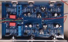
Here is the board in more detail. The left side has the positive and negative regulator, and the right side has the two amplifier halves, with all the power devices fixed on a aluminum profile, which itself is fixed to the heatsink.
There is quite a bit of power dissipation happening here (as it should in true class-A), the heatsinks get lukewarm. Total power dissipation is about 8W - not bad for a headphone amplifier
PS: And yes, for the eagle-eyed among you, you can spot where the smoke was coming out
There is quite a bit of power dissipation happening here (as it should in true class-A), the heatsinks get lukewarm. Total power dissipation is about 8W - not bad for a headphone amplifier
PS: And yes, for the eagle-eyed among you, you can spot where the smoke was coming out
Attachments
Last edited:
Incidentally one version of the F5X Preamp PCB can be used for the circuit in post #5.
The Spice file was also modified from my F5XP simulations.
http://www.diyaudio.com/forums/pass-labs/225230-f5x-preamp-2.html#post3502771
Patrick
The Spice file was also modified from my F5XP simulations.
http://www.diyaudio.com/forums/pass-labs/225230-f5x-preamp-2.html#post3502771
Patrick
Pity that you did not thermally couple the two halves of the balanced circuit.
I wonder how much differential drift you might have without servo ?
Common mode drift is not so critical especially if the bias is 580V.
Patrick
The aluminum profiles of the two halves go to the same heatsink, so eventually the halves will balance, I think. Hard to say what the drift (common or diff mode) is, since I first have to replace a couple resistors (thats where the smoke came out
), will post the results once doneIncidentally one version of the F5X Preamp PCB can be used for the circuit in post #5.
The Spice file was also modified from my F5XP simulations.
http://www.diyaudio.com/forums/pass-labs/225230-f5x-preamp-2.html#post3502771
Patrick
that looks much nicer than mine, especially the back side (that I did not show
)You not only need to thermally couple the MOSFETs, but also the JFETs.
At least they should be very close to each other.
It would be interest to see what drift you get, both differential & common mode, if you disable the servo.
Do you use a servo for each single-ended output, or one for diff and one for CMM ?
I know it is still too early, as you are still prototype testing.
But if you do wish to build again with J74/K170, send me a email via DIYA re PCBs.
Patrick
- Home
- Amplifiers
- Pass Labs
- X5HV - the F5 principle applied to a headphone amp