what Vdc after cap bank you can expect from properly sized xformer , with load (class A amp , common FW construction) is Vac multiplied 1.2 to 1.25
thermistor in primary hot - that's idea - only hot is having small Rdc
CRC is better with smaller C at bridge side , and bigger C at load (amp ) side
change that , and you'll have colder bridge , and final ripple smaller
thermistor in primary hot - that's idea - only hot is having small Rdc
CRC is better with smaller C at bridge side , and bigger C at load (amp ) side
change that , and you'll have colder bridge , and final ripple smaller
Hello everyone,
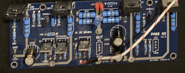
I managed to get an old Aleph 3 (DIY board) however I don't recognize the board we usually have on diyaudiostore so I suspect it's not an official one. I'm currently cleaning it and It plays very nice on my fostex that are quite sensitive (>100db/W) however I hear a small "hum" on the right channel when volume is done. Looking at the board I see 2 variable resistance VR1 (under OYT) and VR2 (under PASS). Does anyone has an idea of this schematic - looking at the one from Nelson this look very closed however I didn't spot this type of variable resistance in the schematic.
Let me know if you have any idea as I suspect a potential small DC.
Attachments
Hello everyone,
I managed to get an old Aleph 3 (DIY board) however I don't recognize the board we usually have on diyaudiostore so I suspect it's not an official one. I'm currently cleaning it and It plays very nice on my fostex that are quite sensitive (>100db/W) however I hear a small "hum" on the right channel when volume is done. Looking at the board I see 2 variable resistance VR1 (under OYT) and VR2 (under PASS). Does anyone has an idea of this schematic - looking at the one from Nelson this look very closed however I didn't spot this type of variable resistance in the schematic.
Let me know if you have any idea as I suspect a potential small DC.
The VR1 500r pot is probably adjustment for AC current gain and the VR2 100k pot is probably adjustment for output stage bias. You would have to verify this by inspecting the board and traces to make sure this is the case, but it makes the most sense. You could also watch the various auctions on Ebay and if you see a board similar in design to the one you have then contact the seller and ask them if they can send you a schematic. You might get lucky and someone may still sell a similar model.
If you have DC on the output then you should be able to measure this to verify and if so then you need to install a better matched input LTP mosfet pair. I doubt that this would be the cause of a hum in the channel. More likely bad wiring and/or grounding practices is the culprit.
- Home
- Amplifiers
- Pass Labs
- Aleph 3? Project.