Greetings DIYAers; I thought some here might be interested in my next build, a pair of Amp Camp Amp monoblocks. While I've gathered a few of the more basic parts, at this point the project is mostly conceptual. That doesn't mean it's vague or undefined. To the contrary it's pretty much fully planned out, and I think the end product will match the design almost exactly.
Electronically, it will be a pretty straightforward ACA build (albeit P2P on perfboard), with the Add-A-Watt mod naturally. I'll also be adding a latching pushbutton power switch circuit.
The fun stuff will be in the chassis design, and its fabrication. I've come up with a short list of design objectives (most of which germinated during, rather than prior to, the design process):
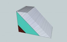
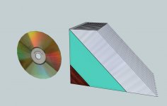
The attached pictures show the finished design.
Fabrication will be a challenge (especially doing two mirror-image monoblocks), but should be well within my capabilities.
This will be a drawn-out build, since I have other demands on my time (bed, bath, & kitchen remodel that's long overdue for completion; cabin bathroom remodel; kids; pets; and a job to pay for it all). But, I'm committed to completing it and I'll post sporadic updates as I make progress.
Electronically, it will be a pretty straightforward ACA build (albeit P2P on perfboard), with the Add-A-Watt mod naturally. I'll also be adding a latching pushbutton power switch circuit.
The fun stuff will be in the chassis design, and its fabrication. I've come up with a short list of design objectives (most of which germinated during, rather than prior to, the design process):
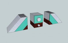
- Outside-the-box thinking. Literally; no rectangular box
- A mix of materials that I like: Metal, Wood, Glass
- No exposed screws or fasteners anywere on the outside of the chassis
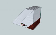
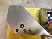
- Low-profile audio connectors
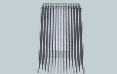
- Stealth ventilation
- No visible power switch
- Glowy!
- Multiple uses: can serve as bookends, door stops, or boot scrapers
- High DHF (Domestic Harmony Factor)
The attached pictures show the finished design.
Fabrication will be a challenge (especially doing two mirror-image monoblocks), but should be well within my capabilities.
This will be a drawn-out build, since I have other demands on my time (bed, bath, & kitchen remodel that's long overdue for completion; cabin bathroom remodel; kids; pets; and a job to pay for it all). But, I'm committed to completing it and I'll post sporadic updates as I make progress.
Attachments
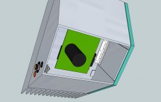
Ventilation detail. Ventilation will be provided by cut-outs at the top and bottom of the heatsink. This is one area where I may have to compromise on my design objectives. If it gets too hot in there, I may have to cut additional ventilation holes in chassis. Or, to avoid that, I may be able to provide active ventilation (laptop fan running at low RPM?).
Attachments
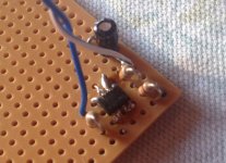
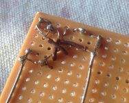
Here's the latching switch circuit wired up. It's based on the circuit found HERE. It uses a little surface-mount dual MOSFET. The one specced on the linked page (IRF7319) didn't quite have the capacity to run the ACA circuit without a relay, so I used IRF7105 which is rated for 25v Vdss/2.3A Id (on the P side). I think that should be able to handle ACA (~20V, 1A); correct me if I'm wrong.
I'm new at this so the layout probably could have been better (a few crossing wires), but I was constrained by the pinout of the dual MOSFET. Anyway, the switch works and it was good practice for when I wire up the main circuit...
I'm new at this so the layout probably could have been better (a few crossing wires), but I was constrained by the pinout of the dual MOSFET. Anyway, the switch works and it was good practice for when I wire up the main circuit...
Attachments
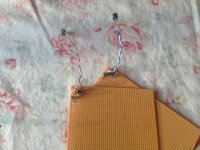
Well, I wired up one channel. Due to space constraints, I arranged the resistors "soldier style." This was both time-consuming, and perhaps beyond my abilities at this point. When I tested the circuit, the LED was throbbing, and the voltage at the drain pin of Q1 was oscillating between ~4V and ~5V, give or take. Obviously I had gotten something wrong in soldering up the circuit.
Rather than spend yet more time trying to diagnose the problem with my limited knowledge, I decided to go the easy route and ordered the boards from the diyAudio store. They're almost ready to go; just watching the mail for the output caps to arrive.
In the meantime, I've gathered up all the rest of the parts and materials I'll need...
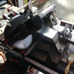
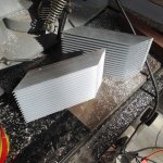
...And today I mounted a new blade in my miter saw, and set about to cutting the heatsinks, with much trepidation. To my surprise and relief, they cut pretty cleanly, with just one cut slightly out-of-square, which I should be able to rectify when I lap the cut faces with sandpaper.
See attached photos if interested. More updates to follow as I make progress...
Rather than spend yet more time trying to diagnose the problem with my limited knowledge, I decided to go the easy route and ordered the boards from the diyAudio store. They're almost ready to go; just watching the mail for the output caps to arrive.
In the meantime, I've gathered up all the rest of the parts and materials I'll need...
...And today I mounted a new blade in my miter saw, and set about to cutting the heatsinks, with much trepidation. To my surprise and relief, they cut pretty cleanly, with just one cut slightly out-of-square, which I should be able to rectify when I lap the cut faces with sandpaper.
See attached photos if interested. More updates to follow as I make progress...
Attachments
Progress is being made, slowly but surely.
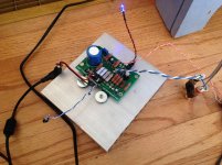
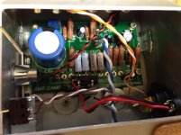
The boards are done and working nicely. The attached pic shows one mounted to a piece of scrap heatsink, and playing the left channel of Over the Hills and Far Away.
It turns out the pulsing of my original perfboard attempt was due to a simple and stupid error; I had accidentally used an IRFP9240 for one of the output devices.
Since I went to PCBs for the amp, I decided to get pushbutton power switch circuits from http://www.pololu.com. The switch is rated for up to 20V, but the description states that it may not turn off reliably at the upper end of its rating. Sure enough, it didn't, so I added a relay and a voltage regulator to bring the voltage to the switch circuit down to 8V, and it now works perfectly.")
I'll be starting on the chassis next. Going to be using some new techniques so it should be educational... Updates to come sporadically as usual.
The boards are done and working nicely. The attached pic shows one mounted to a piece of scrap heatsink, and playing the left channel of Over the Hills and Far Away.
It turns out the pulsing of my original perfboard attempt was due to a simple and stupid error; I had accidentally used an IRFP9240 for one of the output devices.
Since I went to PCBs for the amp, I decided to get pushbutton power switch circuits from http://www.pololu.com. The switch is rated for up to 20V, but the description states that it may not turn off reliably at the upper end of its rating. Sure enough, it didn't, so I added a relay and a voltage regulator to bring the voltage to the switch circuit down to 8V, and it now works perfectly.
I'll be starting on the chassis next. Going to be using some new techniques so it should be educational... Updates to come sporadically as usual.
Attachments
Chassis assembly begins...
My first thought for fabricating the metal part of the chassis was to build a little bending brake and fold the chassis out of a single piece of aluminum. I soon dissuaded myself of that idea because 1) it'd be near impossible to achieve the necessary precision, 2) I wouldn't be able to get nice sharp corners, especially with 1/16" aluminum, and 3) I barely have enough time to build the amps; I don't want to add building a bending brake to my list of projects.
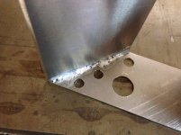
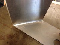
So, I decided I'd assemble the chassis from individual pieces. I went out and got some J-B Weld and aluminum angle stock and set about cutting the pieces. Then I stumbled upon AlumiWeld (more accurately AlumiBraze or AlumiSolder). I went to Harbor Freight and picked some up. With AlumiWeld I could butt-join the pieces without using angle stock, it would be faster, and the chassis pieces would be electrically bonded (not really an issue with ACA). Plus, melting metal is always preferable to using adhesives...
My first attempt was predictably sloppy (first pic) but subsequent joints were nicer (second pic). A couple more pieces to attach and then I can work on attaching the chassis to the heat sinks. Stay tuned...
My first thought for fabricating the metal part of the chassis was to build a little bending brake and fold the chassis out of a single piece of aluminum. I soon dissuaded myself of that idea because 1) it'd be near impossible to achieve the necessary precision, 2) I wouldn't be able to get nice sharp corners, especially with 1/16" aluminum, and 3) I barely have enough time to build the amps; I don't want to add building a bending brake to my list of projects.
So, I decided I'd assemble the chassis from individual pieces. I went out and got some J-B Weld and aluminum angle stock and set about cutting the pieces. Then I stumbled upon AlumiWeld (more accurately AlumiBraze or AlumiSolder). I went to Harbor Freight and picked some up. With AlumiWeld I could butt-join the pieces without using angle stock, it would be faster, and the chassis pieces would be electrically bonded (not really an issue with ACA). Plus, melting metal is always preferable to using adhesives...
My first attempt was predictably sloppy (first pic) but subsequent joints were nicer (second pic). A couple more pieces to attach and then I can work on attaching the chassis to the heat sinks. Stay tuned...
Attachments
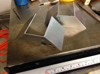
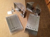
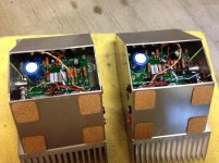
Metalwork done!
The metal parts of the chassis are finished and ready for assembly. But I have work work to do so I won’t be able to put them together tonight After assembling the chaseis, mounting the boards and making all the electrical connections, I’ll still have the woodwork and glasswork to do.
Around 70 holes drilled, 24 of them tapped. I broke a tap in one of the holes in a heat sink, and I couldn’t remove the broken tap without mangling the hole. So mangle the hole I did, then I filled the enlarged hole with JB Weld and drilled and re-tapped it. It’s just for one of the PCB stand-offs, so it should be sufficient.
A few notes about AlumiWeld. As I noted earlier, it’s not really Alumi-“weld” because the base metal isn’t melted and melded with the filler material. And, even though the AlumiWeld rods are rigid a la brazing rods, because brazing generally occurs at temperatures above 840°F, AlumiWeld can more accurately be classified as soldering (it melts at about 720°F).
Unlike the soldering most of us are use to (electronics, or maybe copper pipe soldering), AlumiWeld doesn’t really wick in between the parts being joined, at least in my limited experience. Instead, the adhesion occurs at the fillet. This may be due to my technique. The instructions say to clean the surfaces with a stainless steel wire brush. Since I didn’t have one, I instead abraded the surfaces with 500 grit sand paper and then wiped them with a clean, dry cloth. Flux is not used with AlumiWeld. The unions are plenty strong for this application, but I don’t think I’d use AlumiWeld to build a bike frame. The fact that the AlumiWeld doesn’t wick is visible in the joints on the chassis where a fine line can be seen. Since this is only visible on the back of the chassis, it doesn’t bother me. Incidentally, AlumiWeld can be drilled and tapped, but heatsink being heatsink, I couldn’t get it hot enough to use AlumiWeld on it…
More updates to follow…
The metal parts of the chassis are finished and ready for assembly. But I have work work to do so I won’t be able to put them together tonight
After assembling the chaseis, mounting the boards and making all the electrical connections, I’ll still have the woodwork and glasswork to do.Around 70 holes drilled, 24 of them tapped. I broke a tap in one of the holes in a heat sink, and I couldn’t remove the broken tap without mangling the hole. So mangle the hole I did, then I filled the enlarged hole with JB Weld and drilled and re-tapped it. It’s just for one of the PCB stand-offs, so it should be sufficient.
A few notes about AlumiWeld. As I noted earlier, it’s not really Alumi-“weld” because the base metal isn’t melted and melded with the filler material. And, even though the AlumiWeld rods are rigid a la brazing rods, because brazing generally occurs at temperatures above 840°F, AlumiWeld can more accurately be classified as soldering (it melts at about 720°F).
Unlike the soldering most of us are use to (electronics, or maybe copper pipe soldering), AlumiWeld doesn’t really wick in between the parts being joined, at least in my limited experience. Instead, the adhesion occurs at the fillet. This may be due to my technique. The instructions say to clean the surfaces with a stainless steel wire brush. Since I didn’t have one, I instead abraded the surfaces with 500 grit sand paper and then wiped them with a clean, dry cloth. Flux is not used with AlumiWeld. The unions are plenty strong for this application, but I don’t think I’d use AlumiWeld to build a bike frame. The fact that the AlumiWeld doesn’t wick is visible in the joints on the chassis where a fine line can be seen. Since this is only visible on the back of the chassis, it doesn’t bother me. Incidentally, AlumiWeld can be drilled and tapped, but heatsink being heatsink, I couldn’t get it hot enough to use AlumiWeld on it…
More updates to follow…
Attachments
The metal parts of the chassis are finished and ready for assembly. But I have work work to do so I won’t be able to put them together tonight
Around 70 holes drilled, 24 of them tapped. I broke a tap in one of the holes in a heat sink, and I couldn’t remove the broken tap without mangling the hole. So mangle the hole I did, then I filled the enlarged hole with JB Weld and drilled and re-tapped it. It’s just for one of the PCB stand-offs, so it should be sufficient.
A few notes about AlumiWeld. As I noted earlier, it’s not really Alumi-“weld” because the base metal isn’t melted and melded with the filler material. And, even though the AlumiWeld rods are rigid a la brazing rods, because brazing generally occurs at temperatures above 840°F, AlumiWeld can more accurately be classified as soldering (it melts at about 720°F).
Unlike the soldering most of us are use to (electronics, or maybe copper pipe soldering), AlumiWeld doesn’t really wick in between the parts being joined, at least in my limited experience. Instead, the adhesion occurs at the fillet. This may be due to my technique. The instructions say to clean the surfaces with a stainless steel wire brush. Since I didn’t have one, I instead abraded the surfaces with 500 grit sand paper and then wiped them with a clean, dry cloth. Flux is not used with AlumiWeld. The unions are plenty strong for this application, but I don’t think I’d use AlumiWeld to build a bike frame. The fact that the AlumiWeld doesn’t wick is visible in the joints on the chassis where a fine line can be seen. Since this is only visible on the back of the chassis, it doesn’t bother me. Incidentally, AlumiWeld can be drilled and tapped, but heatsink being heatsink, I couldn’t get it hot enough to use AlumiWeld on it…
More updates to follow…
Nice work!
Nearing Completion
All the tricky stuff is done and the amps are now fully functional. All that remains to be done is fabricating the wood bases and cutting the glass tiles for the front.
Fired them up and they sound pretty darn good to my non-audiophile ears. Can't start using them now, though, because if I do they'll never get finished...
Attachments
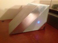
Well, I did what I said I wasn't going to do and I started listening to the amps before I finished them... and just as I thought I never got around to finishing them. Until last night. I wanted to bring them to Burning Amp, so last night I pulled the tile saw out from under the house and started cutting glass tile. Because I hadn't given myself much time, I couldn't clean up the edges as much as I would have liked, but they still came out looking pretty good. Maybe in another seven months I'll get around to finishing up the edges of the tiles.
Anyway, I brought them to Burning Amp today and Mario very kindly let me hook them up to his system in the Pass Pub. I think the consensus was they sounded great (credit to Nelson Pass for the design and Mario for his wonderful speakers; I just built pretty boxes for them).
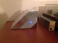
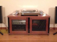
Below are a couple of close-up pix and a pic of the amps in their milieu. Forgive the quality of the pix... the lighting in our living room is lacking.
Anyway, I brought them to Burning Amp today and Mario very kindly let me hook them up to his system in the Pass Pub. I think the consensus was they sounded great (credit to Nelson Pass for the design and Mario for his wonderful speakers; I just built pretty boxes for them).
Below are a couple of close-up pix and a pic of the amps in their milieu. Forgive the quality of the pix... the lighting in our living room is lacking.
Attachments

Anyway, I brought them to Burning Amp today and Mario very kindly let me hook them up to his system in the Pass Pub. I think the consensus was they sounded great (credit to Nelson Pass for the design and Mario for his wonderful speakers; I just built pretty boxes for them).
Below are a couple of close-up pix and a pic of the amps in their milieu. Forgive the quality of the pix... the lighting in our living room is lacking.
I love my ACA amps. Very nice build
- Status
- This old topic is closed. If you want to reopen this topic, contact a moderator using the "Report Post" button.
- Home
- Amplifiers
- Pass Labs
- ACA Concept