
I suspect that the left is really wrong and dangerous.
Both resistors are in the circuit. That is a cathode bypass circuit.
I suspect that the left one is really wrong and dangerous.
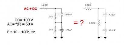
The capacitor on the bottom would be voltage reversed by the DC current.
So If I want to use bi-polar back-to-back capacitors I need the circuit on the right, even if the voltage in the capacitors will result unbalanced (the bottom one will get only 1V acting as a diode, the upper will take DC minus 1V).
Or I would need to mount capacitor on the bottom reversed (so +-+- and not +--+ as it is on the left), but in this case I will not get a bipolar capacitor (so I can use 220uF cap instead of the two). Correct? Any idea to correct balance?
I want to use bipolar caps.
Both resistors are in the circuit. That is a cathode bypass circuit.
I suspect that the left one is really wrong and dangerous.
The capacitor on the bottom would be voltage reversed by the DC current.
So If I want to use bi-polar back-to-back capacitors I need the circuit on the right, even if the voltage in the capacitors will result unbalanced (the bottom one will get only 1V acting as a diode, the upper will take DC minus 1V).
Or I would need to mount capacitor on the bottom reversed (so +-+- and not +--+ as it is on the left), but in this case I will not get a bipolar capacitor (so I can use 220uF cap instead of the two). Correct? Any idea to correct balance?
I want to use bipolar caps.
Last edited:
In a cathode bypass circuit you don't need back-to-back connected electrolytic capacitors....That is a cathode bypass circuit...
In a cathode bypass circuit you don't need back-to-back connected electrolytic capacitors.
True, not mandatory, but really sound better.
Already tested!
Bipolar Electrolytic Capacitors | The Secret Room
In any case the left picture is wrong: I have "measured" consistent positive DC (>> 1 Volt) on the bottom capacitor, which results bad polarized. It doesn't get hot, but I don't trust.
- Status
- This old topic is closed. If you want to reopen this topic, contact a moderator using the "Report Post" button.
- Home
- Amplifiers
- Pass Labs
- Are the two circuits equivalent?