Next to trying to figure out dark matter and dark energy's affect on the universe the next pressing question for me is -- will power factor correction work on Class A amps to make them more efficient (green) and suck less power from the AC wall sockets? I read an interesting article in audio express about an amp manufacturer actually using it in his amp (switching power supply) and it got me thinking.
We all know that are speakers are reactive loads on the amps output and it would seem that this science would work on a linear amp. Has anyone ever tried these circuits on a Pass project? I know that most of us are happy to reduce ripple with voltage regulators so this would be more a project to gain efficiency and reduce heat. Any ideas anyone?
We all know that are speakers are reactive loads on the amps output and it would seem that this science would work on a linear amp. Has anyone ever tried these circuits on a Pass project? I know that most of us are happy to reduce ripple with voltage regulators so this would be more a project to gain efficiency and reduce heat. Any ideas anyone?

The amplifier uses power.
The connection between the mains and the amplifier will not be 100% efficient.
Different topologies will have different losses/efficiencies.
Capacitor input filters, whether into an SMPS or a transformer fed rectifier/capacitor are both terrible for creating distortion of the mains waveform.
Some SMPS have circuitry for reducing this distortion effect.
Many SMPS, especially the lower power types, have no distortion reducing circuitry.
gain efficiency and reduce heat.
Bothered to estimate what the gain will be ? In power, not lb.
(A crane and my 7.5' x 7.5' hot tub arrive tomorrow, 1000+ lbs. Just found out it requires more than 2 circuit breaker/groups, 16A/230Vac, to cook a white man)
Power factor is more a matter of losses in the AC line and transformer
windings, and correction will improve that, but I don't expect that it will
much affect the audio performance.
Many SMPS manufacturers are also including power factor correction in their
products as it is becoming a requirement in various countries and classes of
products.
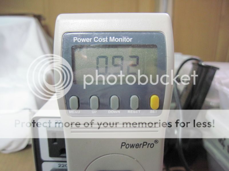
As an indicator of how much energy we are talking about, power factor on
things like Pass Labs and First Watt amplifiers is about 80%.

windings, and correction will improve that, but I don't expect that it will
much affect the audio performance.
Many SMPS manufacturers are also including power factor correction in their
products as it is becoming a requirement in various countries and classes of
products.
As an indicator of how much energy we are talking about, power factor on
things like Pass Labs and First Watt amplifiers is about 80%.
Do you mean something like speaker impedance equalizing?We all know that are speakers are reactive loads on the amps output
No equalizing-just an idea based on an Audio Express article. During my professional years I was responsible for designing and building Pharm and chem plants. Of course all the mains transformers had three phase PF correction but this was the first time I had seen it used on an Audio amp. I understood that it would not make an audio improvement but would lessen the electric consumption. Not a problem for me just an idea. dave
PFC networks can be used to attenuate some noise. The Uberbuss uses one. The details are not available, and I don't know how much attenuation.
Are you just looking to improve noise in the class A? I need to get to work on my dual rail PSU board...
What's the amperage used by all these Pass DIY projects? (The range, v is like 12-40 right?)
Are you just looking to improve noise in the class A? I need to get to work on my dual rail PSU board...
What's the amperage used by all these Pass DIY projects? (The range, v is like 12-40 right?)
rectifier-capacitor input supplies draw current in large pulses for few milliseconds at the peaks of the line V waveform - the pulse current peaks are very much larger than the average or rms current
PFC circuits use switched inductors up front to give near continuous, proportional to line V current - like a pure resistive load
if the high frequency switching transients are well controlled with careful EMI design then the PFC smoothed line current draw means the PFC equipped devices "play nice" with every thing else plugged in nearby
since most EMI measures work reciprocally good PFC supplies will also have better immunity to external EMI sources
It is my understanding that you can improve the rectifier/capacitor circuit
power factor by simply inserting an inductor in series with the line circuit.
Certainly this would smooth the current waveform some.
My PSU build over in the 3116 thread uses a CMC pre-rectification. But if this is done wrong you've got more issues. As I said one will have to be made for dual rail, but it changes things a lot for layout etc.
Seriously though, what's the highest amper any one rail uses for your DIY projects?
I seem to recall either Jung or Curl suggesting a 10uF film cap across the Live/Neutral to absorb some of the HF interference coming in on the mains.It is my understanding that you can improve the rectifier/capacitor circuit
power factor by simply inserting an inductor in series with the line circuit.
Certainly this would smooth the current waveform some.
That HF is effectively the flat topped sinewave that we have to use to feed our transformers.
I'm not too good with AC circuit theory, but here goes.
A pure sinewave supply is just the fundamental 50/60Hz, with no harmonics and no RF interference.
Pass that into your home with a 10uF cap across the lines.
The cap absorbs no power and costs nothing in extra power consumption charges.
So far nothing has been lost. Just pay for the capacitor.
Now buy in our distorted power. It is a sinewave with many high harmonics. If the distortion (showing in the flat topping) is symmetrical, then the harmonics are all odd starting at 150/180Hz and going up from there.
The capacitor will have a lower impedance to these odd harmonics.
The same capacitor current passes at the fundamental frequency, same voltage and same impedance = same current.
At the higher frequencies of the odd harmonics, the capacitor presents a much lower impedance. The capacitor passes relatively more of this odd order harmonic current.
In any "circuit" where there is an impedance in series and an impedance in shunt we have a voltage ladder. If the series and shunt are frequency selective, then that voltage ladder becomes a filter.
A little bit of cable inductance and the 10uF create that filter. It will be a low pass filter and it will attenuate the odd harmonics.
Any attenuation of the harmonics relative to the fundamental will result in the output of the filter containing a LOWER level of odd harmonics relative to the fundamental.
i.e. less distortion.
If the 10uF creates significant filtering of the odd harmonics, particularly those exceeding 9 times the fundamental, then the mains waveform will be LESS distorted and will be closer to the pure sinewave shape.
The addition of the capacitor has "cleaned up" the waveform.
And the capacitor still absorbs no power and still adds nothing to the power bill.
Does that make any scientific sense?
BTW, it was J.Curl's suggestion.
Last edited:
@Andrew. A single cap can do some HF filtering, but cannot reconstitute a since wave that has been rectified to death. And this has nothing to do with the Power factor that is the subject here. PF is a linear(ish) phenomenon due to inductive (motors) or capacitive (fluorescent light) loads. Rectification is non linear and nasty.
PF matters in an office block (hundreds of nasty strip lights or CFLs) or in a factory (big effing motors). But you don't have any of those in a domestic setting generally.
But old fashioned filament bulbs are def better for the true audio loony. Maybe I could sell battery powered LED setups for listening rooms.
I like the idea of power factor correction for that huge power transformer we all aspire to. Voltage waveform leads current waveform in an inductor and the right capacitor would bring this back in line but as someone earlier mentioned, private lines are not scrutinized for power factor. Industrial sites are because of the magnitude of power used. Really big capacitors! I never thought of what effect this waveform mismatch might have downstream i.e. rectification or smoothing. What performance effect might this improve? Noise? Ripple?
the industry uses active PFC terminology also to describe switching power supply input current linearization even if the main effect in rectifier-cap input supplies is current pulse harmonic reduction
it is this use of the term that is relevant in audio power amplifier power supplies where we are creating DC, have to rectify line AC power
it is this use of the term that is relevant in audio power amplifier power supplies where we are creating DC, have to rectify line AC power
- Status
- This old topic is closed. If you want to reopen this topic, contact a moderator using the "Report Post" button.
- Home
- Amplifiers
- Pass Labs
- power factor correction in class a amps